 Xem Studiomeasured geometry
Library › Hardware › Bearings, rails & motion ·
Disc springs (Belleville washers) DIN 2093, series A / B / C: De, Di, t, free height l0, cone height h0, groups 1–3 + cone-solid models
What are the outside diameter, bore, thickness and free height of a DIN 2093 disc spring (Belleville washer), series A, B or C? · Standard part · basis: fasten.it's DIN 2093 table (De, Di, t, l0; 87 rows, one row dropped), Schnorr's handbook (38 DIN series A / B / C rows up to De 40: De, Di, t, l0 agree on every row), ITA Fasteners' series A rows (De 8 to 250; agree except one Di); 15 cone-solid models as files; loads left out
Also called: din 2093 disc spring dimensions, belleville washer size chart, disc spring 20x10.2x1.1, disc spring series a b c, din 2093 series a 25x12.2x1.5, belleville washer 8 mm, disc spring free height l0, disc spring 50x25.4x3, disc spring 100x51x6, disc spring cone height h0, belleville washer step file, disc spring group 1 2 3 thickness, din 2093 40x20.4x2.25
Exact dimensions. Every file is drawn at true size with no tolerance added. The holes and pins that meet another part are listed below under Mating features, with the fit each joint needs; open those by your process's clearance before making the part. Mating features
- length
- 100.0 mm
- width
- 100.0 mm
- height
- 8.2 mm
Notes
- DIN 2093 disc springs (Belleville washers, conical spring washers) come in three series that share the outer diameter De and bore Di but differ in thickness t and free height l0: at each size A is the thickest and C the thinnest (for example 100 × 51: A t 6, B t 3.5, C t 2.7). Rows: series, group, De (h12, max = nominal), Di (H12, min = nominal), thickness t, free height l0 (unloaded overall height) and h0 = l0 − t (computed: the cone height; Schnorr's list prints h0 and l0 − t equals it on every Schnorr row read, and on all 29 of ITA's series A rows).
- Groups (fasten.it): group 1 is t under 1.25 mm (cold formed, radiused edges, no bearing flats); group 2 is 1.25 up to and including 6 mm (cold formed, machined, radiused edges, no bearing flats); group 3 is over 6 mm (machined from forged blanks, with bearing flats and a reduced thickness t'). The group column here follows that thickness rule (fasten.it's own group column puts series A 22.5 × 11.2 and 25 × 12.2 in group 1 although t is 1.25 and 1.5, which is group 2 by its rule). For group 3, ITA prints a reduced thickness t' for series A in brackets after t (125: 7.5, 140: 7.5, 160: 9.4, 180: 9.4, 200: 11.25, 225: 11.25, 250: 13.1); B and C group 3 rows have no t' in the sources read. The width of the bearing flats is not in the sources read.
- Checks: fasten.it, Schnorr and ITA agree on De, Di, t and l0 for every comparable row except the 40 × Di row: fasten.it and Schnorr print Di 20.4 and ITA 20.1, so 20.4 is shown. fasten.it's table also prints a column headed t1 that equals l0 − t on many rows but not on 15 of the rows (for example series C 16 × 8.2 × 0.4: l0 0.9, t1 0.55, but Schnorr's h0 is 0.5), so that column is not used. fasten.it's row for series C 71 × 36 (t printed as 1, l0 4.6) is out of line with its neighbours (C 63: t 1.8, C 80: t 2.25) and is dropped. Schnorr's list continues to De 250 beyond the part read; De 45 and above in series B and C rest on fasten.it alone (ITA covers series A only).
- Loads, deflections and stresses are left out on purpose: fasten.it and ITA print them (F at 25 / 50 / 75 / 100 % of h0, s, stresses) with labels the text extraction did not keep, and a spring's load should come from the maker's curve, not a dimension page. The standard calls out De h12, Di H12 for the sizes; a guide rod or bore must clear Di and De by your own allowance (see Mating features).
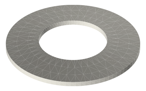
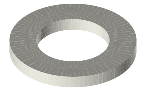
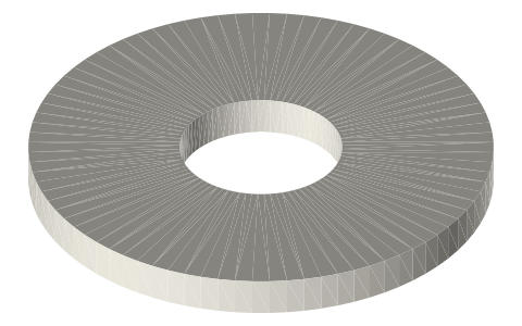
- Files: 15 cone solids, series A, B and C at De 16, 25, 40, 63 and 100 mm (groups 1 and 2 only: group 3 has flats and a reduced thickness not defined by the numbers read). Each is the band between two cones with the axial thickness t, vertical end faces, Di bore and De outside, free height l0, so De, Di, t and l0 are exactly the table values. This is Xem's profile; the standard's own section drawing (square edges to the cone, radii) was not read, so edge radii are not modelled. Schnorr's disc-spring page is linked for CAD per spring.
Disc springs (Belleville washers) DIN 2093, series A / B / C: De… size chart
| series | group | De (mm, h12) | Di (mm, H12) | t (mm) | l0 (mm) | h0 = l0 − t (mm, computed) |
|---|---|---|---|---|---|---|
| C | 1 | 8 | 4.2 | 0.2 | 0.45 | 0.25 |
| B | 1 | 8 | 4.2 | 0.3 | 0.55 | 0.25 |
| A | 1 | 8 | 4.2 | 0.4 | 0.6 | 0.2 |
| C | 1 | 10 | 5.2 | 0.25 | 0.55 | 0.3 |
| B | 1 | 10 | 5.2 | 0.4 | 0.7 | 0.3 |
| A | 1 | 10 | 5.2 | 0.5 | 0.75 | 0.25 |
| C | 1 | 12.5 | 6.2 | 0.35 | 0.8 | 0.45 |
| B | 1 | 12.5 | 6.2 | 0.5 | 0.85 | 0.35 |
| A | 1 | 12.5 | 6.2 | 0.7 | 1 | 0.3 |
| C | 1 | 14 | 7.2 | 0.35 | 0.8 | 0.45 |
| B | 1 | 14 | 7.2 | 0.5 | 0.9 | 0.4 |
| A | 1 | 14 | 7.2 | 0.8 | 1.1 | 0.3 |
| C | 1 | 16 | 8.2 | 0.4 | 0.9 | 0.5 |
| B | 1 | 16 | 8.2 | 0.6 | 1.05 | 0.45 |
| A | 1 | 16 | 8.2 | 0.9 | 1.25 | 0.35 |
| C | 1 | 18 | 9.2 | 0.45 | 1.05 | 0.6 |
| B | 1 | 18 | 9.2 | 0.7 | 1.2 | 0.5 |
| A | 1 | 18 | 9.2 | 1 | 1.4 | 0.4 |
| C | 1 | 20 | 10.2 | 0.5 | 1.15 | 0.65 |
| B | 1 | 20 | 10.2 | 0.8 | 1.35 | 0.55 |
| A | 1 | 20 | 10.2 | 1.1 | 1.55 | 0.45 |
| C | 1 | 22.5 | 11.2 | 0.6 | 1.4 | 0.8 |
| B | 1 | 22.5 | 11.2 | 0.8 | 1.45 | 0.65 |
| A | 2 | 22.5 | 11.2 | 1.25 | 1.75 | 0.5 |
| C | 1 | 25 | 12.2 | 0.7 | 1.6 | 0.9 |
| B | 1 | 25 | 12.2 | 0.9 | 1.6 | 0.7 |
| A | 2 | 25 | 12.2 | 1.5 | 2.05 | 0.55 |
| C | 1 | 28 | 14.2 | 0.8 | 1.8 | 1 |
| B | 1 | 28 | 14.2 | 1 | 1.8 | 0.8 |
| A | 2 | 28 | 14.2 | 1.5 | 2.15 | 0.65 |
| C | 1 | 31.5 | 16.3 | 0.8 | 1.85 | 1.05 |
| B | 2 | 31.5 | 16.3 | 1.25 | 2.15 | 0.9 |
| A | 2 | 31.5 | 16.3 | 1.75 | 2.45 | 0.7 |
| C | 1 | 35.5 | 18.3 | 0.9 | 2.05 | 1.15 |
| B | 2 | 35.5 | 18.3 | 1.25 | 2.25 | 1 |
| A | 2 | 35.5 | 18.3 | 2 | 2.8 | 0.8 |
| C | 1 | 40 | 20.4 | 1 | 2.3 | 1.3 |
| B | 2 | 40 | 20.4 | 1.5 | 2.65 | 1.15 |
| A | 2 | 40 | 20.4 | 2.25 | 3.15 | 0.9 |
| C | 2 | 45 | 22.4 | 1.25 | 2.85 | 1.6 |
| B | 2 | 45 | 22.4 | 1.75 | 3.05 | 1.3 |
| A | 2 | 45 | 22.4 | 2.5 | 3.5 | 1 |
| C | 2 | 50 | 25.4 | 1.25 | 2.85 | 1.6 |
| B | 2 | 50 | 25.4 | 2 | 3.4 | 1.4 |
| A | 2 | 50 | 25.4 | 3 | 4.1 | 1.1 |
| C | 2 | 56 | 28.5 | 1.5 | 3.45 | 1.95 |
| B | 2 | 56 | 28.5 | 2 | 3.6 | 1.6 |
| A | 2 | 56 | 28.5 | 3 | 4.3 | 1.3 |
| C | 2 | 63 | 31 | 1.8 | 4.15 | 2.35 |
| B | 2 | 63 | 31 | 2.5 | 4.25 | 1.75 |
| A | 2 | 63 | 31 | 3.5 | 4.9 | 1.4 |
| B | 2 | 71 | 36 | 2.5 | 4.5 | 2 |
| A | 2 | 71 | 36 | 4 | 5.6 | 1.6 |
| C | 2 | 80 | 41 | 2.25 | 5.2 | 2.95 |
| B | 2 | 80 | 41 | 3 | 5.3 | 2.3 |
| A | 2 | 80 | 41 | 5 | 6.7 | 1.7 |
| C | 2 | 90 | 46 | 2.5 | 5.7 | 3.2 |
| B | 2 | 90 | 46 | 3.5 | 6 | 2.5 |
| A | 2 | 90 | 46 | 5 | 7 | 2 |
| C | 2 | 100 | 51 | 2.7 | 6.2 | 3.5 |
| B | 2 | 100 | 51 | 3.5 | 6.3 | 2.8 |
| A | 2 | 100 | 51 | 6 | 8.2 | 2.2 |
| C | 2 | 112 | 57 | 3 | 6.9 | 3.9 |
| B | 2 | 112 | 57 | 4 | 7.2 | 3.2 |
| A | 2 | 112 | 57 | 6 | 8.5 | 2.5 |
| C | 2 | 125 | 64 | 3.5 | 8 | 4.5 |
| B | 2 | 125 | 64 | 5 | 8.5 | 3.5 |
| A | 3 | 125 | 64 | 8 (t' 7.5) | 10.6 | 2.6 |
| C | 2 | 140 | 72 | 3.8 | 8.7 | 4.9 |
| B | 2 | 140 | 72 | 5 | 9 | 4 |
| A | 3 | 140 | 72 | 8 (t' 7.5) | 11.2 | 3.2 |
| C | 2 | 160 | 82 | 4.3 | 9.9 | 5.6 |
| B | 2 | 160 | 82 | 6 | 10.5 | 4.5 |
| A | 3 | 160 | 82 | 10 (t' 9.4) | 13.5 | 3.5 |
| C | 2 | 180 | 92 | 4.8 | 11 | 6.2 |
| B | 2 | 180 | 92 | 6 | 11.1 | 5.1 |
| A | 3 | 180 | 92 | 10 (t' 9.4) | 14 | 4 |
| C | 2 | 200 | 102 | 5.5 | 12.5 | 7 |
| B | 3 | 200 | 102 | 8 | 13.6 | 5.6 |
| A | 3 | 200 | 102 | 12 (t' 11.25) | 16.2 | 4.2 |
| C | 3 | 225 | 112 | 6.5 | 13.6 | 7.1 |
| B | 3 | 225 | 112 | 8 | 14.5 | 6.5 |
| A | 3 | 225 | 112 | 12 (t' 11.25) | 17 | 5 |
| C | 3 | 250 | 127 | 7 | 14.8 | 7.8 |
| B | 3 | 250 | 127 | 10 | 17 | 7 |
| A | 3 | 250 | 127 | 14 (t' 13.1) | 19.6 | 5.6 |
Mating features
Drawn at the exact size. Open press, slide, run and socket features by your process's clearance (tolerances by process); leave designed gaps and clamp fits as drawn.
| feature | exact | mates with | fit | files |
|---|---|---|---|---|
| Di (H12, min = nominal) and De (h12, max = nominal) | per size, e.g. 50 × 25.4, 100 × 51 mm (series A, B, C share De and Di) | guide rod through the bore and housing bore round the outside: the clearance is your design (not in the sources read) | designed | disc-spring-din-2093-* |
| free height l0 and thickness t | e.g. 50 × 25.4: A l0 4.1 / t 3, B l0 3.4 / t 2, C l0 2.85 / t 1.25 mm | stack height and the space between the seats of a stack | designed | disc-spring-din-2093-* |
Where the files are
Other publishers' files are linked, not hosted. "verify" = check the license at the link before commercial use.
| fasten.it | DIN 2093 disc springs (12/2013, supersedes 01/1992; the page says the norm is cancelled): De h12, Di H12, t, l0 (printed 'h1 cone height') and a 'h0' column, groups 1 to 3, series A / B / C, 87 rows | web | Reference page; numbers only |
| Schnorr | Schnorr handbook for disc springs: DIN 2093 series A / B / C (and Schnorr works-standard sizes) with De, Di, t, l0, h0 for De 6 to 40 mm (38 DIN rows read; Schnorr's list continues in the same layout) | web | Maker handbook; numbers only |
| ITA Fasteners | Disc springs DIN 2093: group, De h12, Di H12, t (and t' for group 3), h0, l0, force, deflection (series A rows, De 8 to 250) | web | Maker page; numbers only |
| Schnorr | Standard disc springs (DIN 2093), maker's product page with CAD data per spring | web, CAD | Maker site terms; CAD per part from the maker verify |
Free files
★ Free files 15 parts. Generated by Xem Studio from the standard; threads are plain cylinders at major diameter. CC BY 4.0. index.json
| disc-spring-din-2093-a-16x8-2x0-9 | DIN 2093 series A disc spring 16 × 8.2 × 0.9 (De × Di × t), free height l0 1.25 mm, so cone height h0 = l0 − t = 0.35 mm; group 1. Drawn as a cone solid: the band between two cones, thickness t measured along the axis, vertical inner and outer end faces (Xem's profile; the standard's own section drawing was not read), unloaded | STEP · STL |
| disc-spring-din-2093-b-16x8-2x0-6 | DIN 2093 series B disc spring 16 × 8.2 × 0.6 (De × Di × t), free height l0 1.05 mm, so cone height h0 = l0 − t = 0.45 mm; group 1. Drawn as a cone solid: the band between two cones, thickness t measured along the axis, vertical inner and outer end faces (Xem's profile; the standard's own section drawing was not read), unloaded | STEP · STL |
| disc-spring-din-2093-c-16x8-2x0-4 | DIN 2093 series C disc spring 16 × 8.2 × 0.4 (De × Di × t), free height l0 0.9 mm, so cone height h0 = l0 − t = 0.5 mm; group 1. Drawn as a cone solid: the band between two cones, thickness t measured along the axis, vertical inner and outer end faces (Xem's profile; the standard's own section drawing was not read), unloaded | STEP · STL |
| disc-spring-din-2093-a-25x12-2x1-5 | DIN 2093 series A disc spring 25 × 12.2 × 1.5 (De × Di × t), free height l0 2.05 mm, so cone height h0 = l0 − t = 0.55 mm; group 2. Drawn as a cone solid: the band between two cones, thickness t measured along the axis, vertical inner and outer end faces (Xem's profile; the standard's own section drawing was not read), unloaded | STEP · STL |
| disc-spring-din-2093-b-25x12-2x0-9 | DIN 2093 series B disc spring 25 × 12.2 × 0.9 (De × Di × t), free height l0 1.6 mm, so cone height h0 = l0 − t = 0.7 mm; group 1. Drawn as a cone solid: the band between two cones, thickness t measured along the axis, vertical inner and outer end faces (Xem's profile; the standard's own section drawing was not read), unloaded | STEP · STL |
| disc-spring-din-2093-c-25x12-2x0-7 | DIN 2093 series C disc spring 25 × 12.2 × 0.7 (De × Di × t), free height l0 1.6 mm, so cone height h0 = l0 − t = 0.9 mm; group 1. Drawn as a cone solid: the band between two cones, thickness t measured along the axis, vertical inner and outer end faces (Xem's profile; the standard's own section drawing was not read), unloaded | STEP · STL |
| disc-spring-din-2093-a-40x20-4x2-25 | DIN 2093 series A disc spring 40 × 20.4 × 2.25 (De × Di × t), free height l0 3.15 mm, so cone height h0 = l0 − t = 0.9 mm; group 2. Drawn as a cone solid: the band between two cones, thickness t measured along the axis, vertical inner and outer end faces (Xem's profile; the standard's own section drawing was not read), unloaded | STEP · STL |
| disc-spring-din-2093-b-40x20-4x1-5 | DIN 2093 series B disc spring 40 × 20.4 × 1.5 (De × Di × t), free height l0 2.65 mm, so cone height h0 = l0 − t = 1.15 mm; group 2. Drawn as a cone solid: the band between two cones, thickness t measured along the axis, vertical inner and outer end faces (Xem's profile; the standard's own section drawing was not read), unloaded | STEP · STL |
| disc-spring-din-2093-c-40x20-4x1 | DIN 2093 series C disc spring 40 × 20.4 × 1 (De × Di × t), free height l0 2.3 mm, so cone height h0 = l0 − t = 1.3 mm; group 1. Drawn as a cone solid: the band between two cones, thickness t measured along the axis, vertical inner and outer end faces (Xem's profile; the standard's own section drawing was not read), unloaded | STEP · STL |
| disc-spring-din-2093-a-63x31x3-5 | DIN 2093 series A disc spring 63 × 31 × 3.5 (De × Di × t), free height l0 4.9 mm, so cone height h0 = l0 − t = 1.4 mm; group 2. Drawn as a cone solid: the band between two cones, thickness t measured along the axis, vertical inner and outer end faces (Xem's profile; the standard's own section drawing was not read), unloaded | STEP · STL |
| disc-spring-din-2093-b-63x31x2-5 | DIN 2093 series B disc spring 63 × 31 × 2.5 (De × Di × t), free height l0 4.25 mm, so cone height h0 = l0 − t = 1.75 mm; group 2. Drawn as a cone solid: the band between two cones, thickness t measured along the axis, vertical inner and outer end faces (Xem's profile; the standard's own section drawing was not read), unloaded | STEP · STL |
| disc-spring-din-2093-c-63x31x1-8 | DIN 2093 series C disc spring 63 × 31 × 1.8 (De × Di × t), free height l0 4.15 mm, so cone height h0 = l0 − t = 2.35 mm; group 2. Drawn as a cone solid: the band between two cones, thickness t measured along the axis, vertical inner and outer end faces (Xem's profile; the standard's own section drawing was not read), unloaded | STEP · STL |
| disc-spring-din-2093-a-100x51x6 | DIN 2093 series A disc spring 100 × 51 × 6 (De × Di × t), free height l0 8.2 mm, so cone height h0 = l0 − t = 2.2 mm; group 2. Drawn as a cone solid: the band between two cones, thickness t measured along the axis, vertical inner and outer end faces (Xem's profile; the standard's own section drawing was not read), unloaded | STEP · STL |
| disc-spring-din-2093-b-100x51x3-5 | DIN 2093 series B disc spring 100 × 51 × 3.5 (De × Di × t), free height l0 6.3 mm, so cone height h0 = l0 − t = 2.8 mm; group 2. Drawn as a cone solid: the band between two cones, thickness t measured along the axis, vertical inner and outer end faces (Xem's profile; the standard's own section drawing was not read), unloaded | STEP · STL |
| disc-spring-din-2093-c-100x51x2-7 | DIN 2093 series C disc spring 100 × 51 × 2.7 (De × Di × t), free height l0 6.2 mm, so cone height h0 = l0 − t = 3.5 mm; group 2. Drawn as a cone solid: the band between two cones, thickness t measured along the axis, vertical inner and outer end faces (Xem's profile; the standard's own section drawing was not read), unloaded | STEP · STL |
https://xemstudio.com/mcp to Claude, ChatGPT, Cursor or any MCP client (free, no account, one minute) and it can look up exact sizes, mating fits and free STEP/STL from every chat.Plain text: sheet.txt · JSON: /api/geometry?object=disc-springs-din-2093
Fits with
Questions
What are the dimensions of a 50 × 25.4 DIN 2093 disc spring?
Series A: t 3, l0 4.1 (h0 1.1); series B: t 2, l0 3.4 (h0 1.4); series C: t 1.25, l0 2.85 (h0 1.6) mm, De 50 h12 and Di 25.4 H12.
What is the difference between series A, B and C?
Same De and Di, different t and l0: at each size here A is the thickest of the three and C the thinnest (50 × 25.4: t 3, 2, 1.25 mm).
How do I get h0 from l0?
h0 = l0 − t; Schnorr's list prints h0 and l0 − t equals it on every row read.