 Xem Studiomeasured geometry
Library › Tri-clamp & pipe › Pipe, tube & threads ·
ISO 6432 round mini cylinders, bore 8-25: rod thread, rod Ø, nose thread M12/M16/M22, port + 2 hole gauges
What are the rod thread, nose (barrel) thread and port of an ISO 6432 8, 10, 12, 16, 20 or 25 mm round pneumatic cylinder? · Standard part · basis: Riegler's ISO 6432 datasheet cross-checked against Emerson ASCO's catalogue and AutomationDirect's spec sheet; two Xem-drawn hole gauges
Also called: iso 6432 dimensions, iso 6432 cylinder mounting, mini air cylinder 16 mm rod thread, iso 6432 nose thread m16x1.5, dsnu 16 dimensions, round pneumatic cylinder 20 mm rod thread m8, festo dsnu mounting nut thread, smc cm2 rod thread, airtac mini cylinder 25 mm port, pneumatic cylinder 12 mm bore nose thread, mini cylinder panel hole size, iso 6432 25 mm rod m10x1.25
Exact dimensions. Every file is drawn at true size with no tolerance added. The holes and pins that meet another part are listed below under Mating features, with the fit each joint needs; open those by your process's clearance before making the part. Mating features
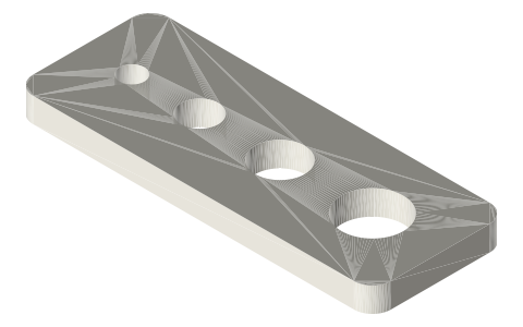
- length
- 74.0 mm
- width
- 34.0 mm
- height
- 4.0 mm
Notes
- ISO 6432:1985 is the 10 bar round mini cylinder series, bores 8, 10, 12, 16, 20, 25 mm (iTeh scope page). The body is a round tube with a threaded nose; the cylinder bolts through a panel or bracket hole with a nut on the nose thread (the standard also lists flange, rear-eye and angle mounts, whose tables are OCR-garbled in the sample and are not used).
- Rows are what at least two sources print. Rod thread: M4, M4, M6, M6, M8, M10×1.25 (Riegler, Emerson for 10 to 25; AutomationDirect prints the clevis / eye thread M6, M6, M8, M10×1.25 for bores 12 to 25). Nose thread BE: M12×1.25 (8, 10), M16×1.5 (12, 16), M22×1.5 (20, 25) (Riegler, Emerson; AutomationDirect's mounting nuts M16×1.5 for 12 and 16 and M22×1.5 for 20 and 25). Port: M5 (10 to 16) and G1/8 (20, 25) (Emerson, AutomationDirect; bore 8 is M5 on Riegler alone). AM (12, 12, 16, 16, 20, 22): Riegler's AM column and Emerson's F column agree.
- Rod diameter: 6, 6, 8, 10 mm for bores 12 to 25 (AutomationDirect); 4 mm for bores 8 and 10 is read from Riegler's D1 column alone (its 12 to 25 values 6, 6, 8, 10 match AutomationDirect), so it has one source. Riegler's row for bore 16 shows G1/8 in an unlabelled column near the port; Emerson and AutomationDirect both give M5, so M5 is used.
- Not tabulated: lengths (stroke, overall, XC), nut hex sizes and the mounting-bracket dimensions: column letters are garbled or undefined in the text read, and no second source agreed. The inch series follows ISO 22811 (footnote of the ISO 6432 sample) and is not on this page.
- Files: two hole gauges. The nose-thread gauge has holes at Ø12, Ø16 and Ø22 (the nominal major diameters of the three nose threads), the rod-thread gauge Ø4, Ø6, Ø8 and Ø10 (rod threads, plain holes). Plate thickness 4 mm, hole spacing and margin 6 mm are Xem choices. A real panel hole that a nose thread passes through is a clearance fit; apply your process allowance to these features. Bigger cylinders: iso-15552-pneumatic-cylinder-mounting.
ISO 6432 round mini cylinders, bore 8-25: rod thread, rod Ø, nose… size chart
| bore | rod Ø | rod thread KK | nose thread BE | AM (rod thread length) | port |
|---|---|---|---|---|---|
| 8 | 4 | M4 | M12×1.25 | 12 | M5 |
| 10 | 4 | M4 | M12×1.25 | 12 | M5 |
| 12 | 6 | M6 | M16×1.5 | 16 | M5 |
| 16 | 6 | M6 | M16×1.5 | 16 | M5 |
| 20 | 8 | M8 | M22×1.5 | 20 | G1/8 |
| 25 | 10 | M10×1.25 | M22×1.5 | 22 | G1/8 |
Mating features
Drawn at the exact size. Open press, slide, run and socket features by your process's clearance (tolerances by process); leave designed gaps and clamp fits as drawn.
| feature | exact | mates with | fit | files |
|---|---|---|---|---|
| nose-thread holes (nominal major Ø) | Ø12 / Ø16 / Ø22 mm (M12×1.25, M16×1.5, M22×1.5) | cylinder nose thread and its mounting nut (bore 8-10 / 12-16 / 20-25) | slide | iso-6432-nose-* |
| rod-thread holes (nominal major Ø) | Ø4 / Ø6 / Ø8 / Ø10 mm (M4, M6, M8, M10×1.25) | rod end thread (rod-eye, clevis, floating joint) | designed | iso-6432-rod-* |
Where the files are
Other publishers' files are linked, not hosted. "verify" = check the license at the link before commercial use.
| Riegler | ISO 6432 round cylinders datasheet 18-3: AM, BE (nose thread), D1, EE, KK, bore 8 to 25 | web | Maker datasheet; numbers only. Column letters partly garbled in the text read |
| Emerson ASCO | Series ISO 6432 cylinder catalogue: A (rod thread), B (nose thread), F, R (port) for bore 10 to 25 | web | Maker catalogue; numbers only. Letters not defined in the text read |
| AutomationDirect | ISO 6432 stainless round-body cylinders: rod diameter, port size, mounting nut and clevis / eye thread, bore 12 to 25 | web | Maker spec sheet; numbers only |
| ISO / iTeh | ISO 6432:1985 Pneumatic fluid power: single rod cylinders, 10 bar (1000 kPa) series, bores from 8 to 25 mm, mounting dimensions (scope and sample pages) | web | Standard scope; the sample's tables are OCR-garbled and were not used for numbers |
| McMaster-Carr | ISO 15552 air cylinders and their clevis / pivot brackets (free STEP/IGES per part, for your own design use; no redistribution) | STEP, IGES, PDF | McMaster-Carr site terms: personal design use, no redistribution verify |
Free files
★ Free files 2 parts. Generated by Xem Studio from the standard; threads are plain cylinders at major diameter. CC BY 4.0. index.json
| iso-6432-nose-thread-hole-gauge-m12-m16-m22 | nose-thread hole gauge plate, 74.0 × 34.0 × 4 mm, three holes at the nominal major diameter of the cylinder nose threads M12×1.25, M16×1.5 and M22×1.5 (Ø12, Ø16, Ø22; a thread drawn as a plain hole), smallest first, 6 mm between hole edges and 6 mm of plate round the largest hole; plate thickness and spacing are Xem choices. A panel hole for a nut-mounted cylinder is a different, clearance size: open it for your fit | STEP · STL |
| iso-6432-rod-thread-hole-gauge-m4-m6-m8-m10 | rod-thread hole gauge plate, 58.0 × 22.0 × 4 mm, four holes at the nominal major diameter of the rod threads M4, M6, M8 and M10×1.25 (Ø4, Ø6, Ø8, Ø10; a thread drawn as a plain hole), smallest first, 6 mm between hole edges and 6 mm of plate round the largest hole; plate thickness and spacing are Xem choices | STEP · STL |
https://xemstudio.com/mcp to Claude, ChatGPT, Cursor or any MCP client (free, no account, one minute) and it can look up exact sizes, mating fits and free STEP/STL from every chat.Plain text: sheet.txt · JSON: /api/geometry?object=iso-6432-round-pneumatic-cylinder-mounting
Fits with

Questions
What is the nose thread of a 16 mm ISO 6432 cylinder?
M16×1.5, with a mounting nut of the same thread; rod thread M6 on a Ø6 rod, port M5.
What thread is the rod of a 25 mm round pneumatic cylinder?
M10×1.25 on a Ø10 rod; nose thread M22×1.5 and port G1/8.
What panel hole do I need for a 20 mm mini cylinder?
The nose thread is M22×1.5, so the panel hole has to clear Ø22; the files here are drawn at exactly Ø22 and need your process's clearance added.