 Xem Studiomeasured geometry
Library › Tri-clamp & pipe › Pipe, tube & threads ·
ISO 15552 pneumatic cylinder mounting, bore 32-100: rod thread KK, rod Ø, TG hole pattern, RT thread, spigot B, port + 6 mounting templates
What are the rod thread, mounting hole pattern (TG) and end-cap thread of an ISO 15552 (ISO 6431, VDMA 24562) 32, 40, 50, 63, 80 or 100 mm pneumatic cylinder? · Standard part · basis: Tameson, Almotion, Riegler, pneumatiek.nl and Festo ISO 15552 tables compared (a value is listed only where at least three agree), with McMaster-Carr's ISO 15552 bracket hole spacing as a cross-check; six Xem-drawn mounting-pattern templates
Also called: iso 15552 dimensions, iso 15552 mounting dimensions, iso 6431 cylinder dimensions, vdma 24562 cylinder, pneumatic cylinder rod thread m10x1.25, 63 mm pneumatic cylinder mounting holes, air cylinder 40 mm bore rod thread, iso 15552 tg dimension, iso 15552 32 mm bore, festo dsbc 50 mounting holes, smc c96 mounting hole spacing, iso 15552 80 mm rt thread, pneumatic cylinder end cap bolt pattern, airt
Exact dimensions. Every file is drawn at true size with no tolerance added. The holes and pins that meet another part are listed below under Mating features, with the fit each joint needs; open those by your process's clearance before making the part. Mating features
- length
- 137.0 mm
- width
- 113.0 mm
- height
- 8.0 mm
Notes
- ISO 15552 (10 bar tie-rod / profile cylinders; ISO 15552:2018 replaces ISO 6431, DIN ISO 6431 and VDMA 24562, per Rowse Pneumatics) fixes the bore series 32, 40, 50, 63, 80, 100, 125 ... 320 mm and the mounting interface, so brackets, clevises and rod ends from different makers swap. Festo, SMC, Airtac, Camozzi, Parker, Aventics and others build to it. Rows here are bores 32 to 100 mm; 125 to 320 mm exist in the sources but are not tabulated.
- Column letters follow the sources, which print them without defining them in the text read; the usual reading is: MM = piston rod diameter. KK = rod end thread (fine metric). AM = rod thread length. B (d11) = the cap centring diameter a flange or bracket locates on. TG = the square hole pattern: the four tapped end-cap holes lie on a TG × TG square (hole-to-hole distance TG in both directions; McMaster's brackets confirm the 32.5 / 38 / 46.5 / 56.5 / 72 mm centre-to-centre spacing). RT = thread of those four holes. EE = air port thread (BSP parallel, G). WH = rod-end shoulder dimension from the front-cap face.
- Agreement between sources. MM 12, 16, 20, 20, 25, 25 (Tameson, Festo). KK and AM (Tameson, Almotion, Riegler). B (Tameson, Almotion, pneumatiek.nl, Festo). TG 32.5, 38, 46.5, 56.5, 72, 89 and RT M6, M6, M8, M8, M10, M10 (Almotion, Riegler, pneumatiek.nl, Festo, Tameson). EE (Tameson, Almotion, Riegler). WH 26, 30, 37, 37, 46, 51 (Almotion, Riegler, pneumatiek.nl). McMaster-Carr lists ISO 15552 clevis / pivot brackets with 4 holes at 32.5, 38, 46.5, 56.5 and 72 mm centre-to-centre for bores 32 to 80 (bore 100 not on the page read): bracket hole Ø6 / 6.6 (32, 40), Ø9 (50, 63), Ø11 (80) on the stainless bracket, Ø6 (32, 40) and Ø8 (63) on the aluminium one.
- Where makers differ and no single value is published: the profile width E varies by maker by a few millimetres: Almotion 47, 52, 65, 75, 95, 115; Riegler 47, 53, 65, 75, 95, 115; pneumatiek.nl 46, 54, 64.5, 75.5, 94, 111; Tameson (its column M, beside its TG column) 46.5, 54, 67, 75, 93, 110. Festo prints WH 25, 28.7, 35.6, 35.9, 45.4, 49.3 against the 26, 30, 37, 37, 46, 51 above, and ZJ and VD differ in all sources (VD: 4 on Almotion, 6.5 to 14 on pneumatiek.nl, 10 to 19.2 on Festo; ZJ 119.1 to 124, 120 on Riegler for bore 32). So E, VD and ZJ are left out; read them from the datasheet of the cylinder you buy. Foot, flange and clevis bracket dimensions are also maker pages and are not tabulated.
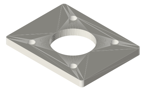
- Files: six mounting-pattern templates, one per bore. Each is a square plate with the four holes at the TG square drawn at the nominal major diameter of RT (a thread drawn as a plain hole, M6 = Ø6, M8 = Ø8, M10 = Ø10) and a centre hole at the spigot diameter B. They are the bracket side of the joint: open the four holes to your bolt's clearance (McMaster's brackets use Ø6.6 / Ø9 / Ø11 for M6 / M8 / M10). Plate = (TG + 48) × (TG + 24) mm, thickness 8 mm, corner radius 3 mm: Xem choices (the holes sit on the plate centre). The cylinder body is not drawn: E and the end-cap shape are not one published set of numbers.
- Port sizes: the tables print BSP parallel (G1/8 to G1/2). NPT versions exist from some makers; see npt-bsp-thread-envelopes. Tube for the port fittings: push-to-connect-fitting-sizes. Round mini cylinders 8-25 mm: iso-6432-round-pneumatic-cylinder-mounting.
ISO 15552 pneumatic cylinder mounting, bore 32-100: rod thread KK… size chart
| bore | rod Ø MM | rod thread KK | AM (rod thread length) | spigot B (d11) | TG (square hole pattern) | RT (end-cap thread) | EE (port) | WH |
|---|---|---|---|---|---|---|---|---|
| 32 | 12 | M10×1.25 | 22 | 30 | 32.5 | M6 | G1/8 | 26 |
| 40 | 16 | M12×1.25 | 24 | 35 | 38 | M6 | G1/4 | 30 |
| 50 | 20 | M16×1.5 | 32 | 40 | 46.5 | M8 | G1/4 | 37 |
| 63 | 20 | M16×1.5 | 32 | 45 | 56.5 | M8 | G3/8 | 37 |
| 80 | 25 | M20×1.5 | 40 | 45 | 72 | M10 | G3/8 | 46 |
| 100 | 25 | M20×1.5 | 40 | 55 | 89 | M10 | G1/2 | 51 |
Mating features
Drawn at the exact size. Open press, slide, run and socket features by your process's clearance (tolerances by process); leave designed gaps and clamp fits as drawn.
| feature | exact | mates with | fit | files |
|---|---|---|---|---|
| 4 holes on the TG square (drawn at the RT nominal major Ø) | TG 32.5 / 38 / 46.5 / 56.5 / 72 / 89 mm square, Ø per file: 6 / 6 / 8 / 8 / 10 / 10 (bore 32 / 40 / 50 / 63 / 80 / 100) | tapped end-cap holes RT of the cylinder (M6 / M6 / M8 / M8 / M10 / M10). A bracket's bolt clearance holes are a separate size: McMaster's ISO 15552 stainless brackets use Ø6.6 (32, 40), Ø9 (50, 63), Ø11 (80) | designed | iso-15552-end-cap-template-* |
| centre hole at spigot B (d11 nominal) | Ø30 / 35 / 40 / 45 / 45 / 55 mm (bore 32 / 40 / 50 / 63 / 80 / 100) | front-cap centring spigot ØB d11 of the cylinder | slide | iso-15552-end-cap-template-* |
Where the files are
Other publishers' files are linked, not hosted. "verify" = check the license at the link before commercial use.
Free files
★ Free files 6 parts. Generated by Xem Studio from the standard; threads are plain cylinders at major diameter. CC BY 4.0. index.json
| iso-15552-end-cap-template-32mm | mounting-pattern template for an ISO 15552 Ø32 cylinder end cap: 80.5 × 56.5 × 8 mm plate, four holes on the TG = 32.5 mm square drawn at the nominal major diameter of the end-cap thread M6 (Ø6; a through-hole for a bolt is a different size, open it for your fastener), one centre hole at the spigot B = Ø30 (d11 nominal). Plate size, thickness and corner radius are Xem choices | STEP · STL |
| iso-15552-end-cap-template-40mm | mounting-pattern template for an ISO 15552 Ø40 cylinder end cap: 86 × 62.0 × 8 mm plate, four holes on the TG = 38 mm square drawn at the nominal major diameter of the end-cap thread M6 (Ø6; a through-hole for a bolt is a different size, open it for your fastener), one centre hole at the spigot B = Ø35 (d11 nominal). Plate size, thickness and corner radius are Xem choices | STEP · STL |
| iso-15552-end-cap-template-50mm | mounting-pattern template for an ISO 15552 Ø50 cylinder end cap: 94.5 × 70.5 × 8 mm plate, four holes on the TG = 46.5 mm square drawn at the nominal major diameter of the end-cap thread M8 (Ø8; a through-hole for a bolt is a different size, open it for your fastener), one centre hole at the spigot B = Ø40 (d11 nominal). Plate size, thickness and corner radius are Xem choices | STEP · STL |
| iso-15552-end-cap-template-63mm | mounting-pattern template for an ISO 15552 Ø63 cylinder end cap: 104.5 × 80.5 × 8 mm plate, four holes on the TG = 56.5 mm square drawn at the nominal major diameter of the end-cap thread M8 (Ø8; a through-hole for a bolt is a different size, open it for your fastener), one centre hole at the spigot B = Ø45 (d11 nominal). Plate size, thickness and corner radius are Xem choices | STEP · STL |
| iso-15552-end-cap-template-80mm | mounting-pattern template for an ISO 15552 Ø80 cylinder end cap: 120 × 96.0 × 8 mm plate, four holes on the TG = 72 mm square drawn at the nominal major diameter of the end-cap thread M10 (Ø10; a through-hole for a bolt is a different size, open it for your fastener), one centre hole at the spigot B = Ø45 (d11 nominal). Plate size, thickness and corner radius are Xem choices | STEP · STL |
| iso-15552-end-cap-template-100mm | mounting-pattern template for an ISO 15552 Ø100 cylinder end cap: 137 × 113.0 × 8 mm plate, four holes on the TG = 89 mm square drawn at the nominal major diameter of the end-cap thread M10 (Ø10; a through-hole for a bolt is a different size, open it for your fastener), one centre hole at the spigot B = Ø55 (d11 nominal). Plate size, thickness and corner radius are Xem choices | STEP · STL |
https://xemstudio.com/mcp to Claude, ChatGPT, Cursor or any MCP client (free, no account, one minute) and it can look up exact sizes, mating fits and free STEP/STL from every chat.Plain text: sheet.txt · JSON: /api/geometry?object=iso-15552-pneumatic-cylinder-mounting
Fits with

Questions
What is the mounting hole pattern of a 50 mm ISO 15552 cylinder?
Four M8 end-cap holes on a 46.5 mm square (TG = 46.5, RT = M8); the front-cap centring spigot is Ø40 d11.
What rod thread does a 32 mm ISO 15552 cylinder have?
M10×1.25 on a Ø12 rod, thread length AM 22 mm (Tameson, Almotion and Riegler agree on the thread and AM; Tameson and Festo on the rod diameter).
Is ISO 15552 the same as ISO 6431 and VDMA 24562?
ISO 15552:2018 replaces ISO 6431, DIN ISO 6431 and VDMA 24562 (Rowse Pneumatics); the bore series and mounting interface stay the same for 32 to 320 mm.
Is the profile width the same on every make?
No. E differs by a few millimetres between makers (for bore 100: 111, 115 and 110 mm in the sources read), so read E from the datasheet of the cylinder; the TG pattern is the shared interface.