 Xem Studiomeasured geometry
Library › Tri-clamp & pipe › Pipe, tube & threads ·
Malleable iron threaded fittings, Class 150 (ASME B16.3): elbow, tee, coupling and union dimensions, NPS 1/8 to 6
What are the center-to-end dimensions of a Class 150 malleable iron (black iron) 90° elbow, 45° elbow, tee, coupling and union? · Standard part · basis: Anvil International's published spec sheets (FIG. 3101 90° elbow, 3102 45° elbow, 3105 tee, 3121 coupling, 463 union) and Smith-Cooper's catalogs for tee and coupling outside diameters; inches, with mm as printed by Anvil or converted at 25.4
Also called: malleable iron fitting dimensions, black iron pipe fitting dimensions, b16.3 malleable fitting, class 150 malleable elbow dimensions, black iron elbow center to end, 1/2 black iron tee dimensions, malleable iron coupling length, black iron 90 elbow dimensions, 150 lb malleable tee outside diameter, ground joint union length, malleable iron union dimensions, 1 inch black iron elbow, 3/4 black pipe
Exact dimensions. Every file is drawn at true size with no tolerance added. The holes and pins that meet another part are listed below under Mating features, with the fit each joint needs; open those by your process's clearance before making the part. Mating features
- sizes
- 16 in table
Notes
- Class 150 'standard' malleable iron fittings (ASTM A197, NPT threads per ASME B1.20.1) are made to ASME B16.3; unions are ASME B16.39. Anvil prints one dimension per figure: A, the centre to the end of the threaded opening for elbows and tees, and the end-to-end length for the coupling. Smith-Cooper's catalogs agree with Anvil for the 90° tee A and the coupling length for every size they share (for example NPS 1/2: 1.12 in tee, 1.34 in coupling).
- Smith-Cooper also prints the outside diameter of the tee (B) and the minimum outside diameter of the coupling (A): NPS 1/2 tee OD 1.20 in, NPS 1 1.77 in, NPS 2 2.96 in. They are the same series, so the coupling OD min equals the tee B for NPS 1/8 to 5. A 6 in coupling is printed 7.36 in against a 7.77 in tee band; that row is left out of the coupling column and flagged here. Nominal cast wall thickness is also printed (0.10 in at 1/2, 0.17 in at 2); it is the wall away from the threads and the thread-end walls are thicker, so it is not used to draw a bore.
- Not tabulated by Anvil's sheets read: elbow and tee outside diameters from Anvil (Smith-Cooper's OD above is used), 3-1/2 and 5 in elbows (Anvil omits them), and Class 300 (the 300 lb series is a separate B16.3 table). Anvil's sheets stop at NPS 6, Smith-Cooper at NPS 8 for tees. The union column is Anvil FIG. 463 (bronze-to-iron seat, Class 150, ASME B16.39), end-to-end in mm as printed with the inch fraction; B16.39 is its own standard, not B16.3.
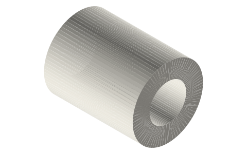
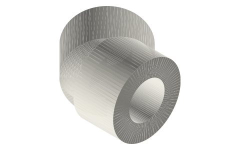
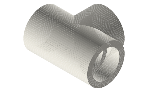
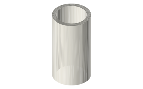
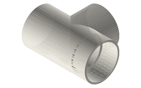
- Files: Class 150 straight tees and couplings at NPS 1/4, 1/2, 3/4 and 1: Xem-drawn envelopes of the published values. The tee is cylinders of the maker's outside diameter B meeting at a sphere, out to A on run and branch; the coupling is a tube of the maker's minimum OD and the published end-to-end length. Threads are plain bores: the bore is the NPT tap-drill size from npt-bsp-thread-envelopes (Ø11.1 / 18.3 / 23.4 / 29.4 mm), thread and band are not drawn. Elbows have no file: the elbow outside diameter is not printed in the sheets read.
- Why sizes stop at 1 in for files: the tap-drill table this site already carries (npt-bsp-thread-envelopes) ends at 1 in; larger sizes would need NPT tap-drill sizes from a source read. Dimensions in the table cover every size the sheets print.
- Several Smith-Cooper coupling inside-diameter entries are plain misprints (a 4 in coupling is printed with an inside diameter of 0.54 / 0.58 in) and are not used.
Malleable iron threaded fittings, Class 150 (ASME B16.3): elbow… size chart
| NPS | 90° elbow A, in (mm) | 45° elbow A, in (mm) | tee A, in (mm) | tee OD B, in (mm) | nominal cast wall, in | coupling end-to-end, in (mm) | coupling OD min, in (mm) | union end-to-end (Fig. 463) |
|---|---|---|---|---|---|---|---|---|
| 1/8 | 0.69 (17.5) | 0.63 (16.0) | 0.69 (17.5) | 0.69 (17.5) | 0.09 | 0.96 (24.4) | 0.69 (17.5) | 33 mm (1 5/16 in) |
| 1/4 | 0.81 (20.6) | 0.73 (18.5) | 0.81 (20.6) | 0.84 (21.3) | 0.09 | 1.06 (26.9) | 0.84 (21.3) | 47 mm (1 13/16 in) |
| 3/8 | 0.95 (24.1) | 0.80 (20.3) | 0.95 (24.1) | 1.01 (25.7) | 0.10 | 1.16 (29.5) | 1.01 (25.7) | 47 mm (1 13/16 in) |
| 1/2 | 1.12 (28.4) | 0.88 (22.4) | 1.12 (28.4) | 1.20 (30.5) | 0.10 | 1.34 (34.0) | 1.20 (30.5) | 49 mm (1 15/16 in) |
| 3/4 | 1.31 (33.3) | 0.98 (24.9) | 1.31 (33.3) | 1.46 (37.1) | 0.12 | 1.52 (38.6) | 1.46 (37.1) | 52 mm (2 1/16 in) |
| 1 | 1.50 (38.1) | 1.12 (28.4) | 1.50 (38.1) | 1.77 (45.0) | 0.13 | 1.67 (42.4) | 1.77 (45.0) | 62 mm (2 7/16 in) |
| 1-1/4 | 1.75 (44.4) | 1.29 (32.8) | 1.75 (44.4) | 2.15 (54.6) | 0.14 | 1.93 (49.0) | 2.15 (54.6) | 67 mm (2 5/8 in) |
| 1-1/2 | 1.94 (49.3) | 1.43 (36.3) | 1.94 (49.3) | 2.43 (61.7) | 0.15 | 2.15 (54.6) | 2.43 (61.7) | 70 mm (2 3/4 in) |
| 2 | 2.25 (57.1) | 1.68 (42.7) | 2.25 (57.1) | 2.96 (75.2) | 0.17 | 2.53 (64.3) | 2.96 (75.2) | 75 mm (2 15/16 in) |
| 2-1/2 | 2.70 (68.6) | 1.95 (49.5) | 2.70 (68.6) | 3.59 (91.2) | 0.21 | 2.88 (73.2) | 3.59 (91.2) | 92 mm (3 5/8 in) |
| 3 | 3.08 (78.2) | 2.17 (55.1) | 3.08 (78.2) | 4.28 (108.7) | 0.23 | 3.18 (80.8) | 4.28 (108.7) | 95 mm (3 3/4 in) |
| 3-1/2 | — | — | 3.42 (86.9) | 4.84 (122.9) | 0.25 | 3.50 (88.9) | 4.84 (122.9) | — |
| 4 | 3.79 (96.3) | 2.61 (66.3) | 3.79 (96.3) | 5.40 (137.2) | 0.26 | 3.69 (93.7) | 5.40 (137.2) | — |
| 5 | — | — | 4.50 (114.3) | 6.58 (167.1) | 0.30 | — | — | — |
| 6 | 5.13 (130.3) | 3.46 (87.9) | 5.13 (130.3) | 7.77 (197.4) | 0.34 | — | — | — |
| 8 | — | — | 6.50 (165.1) | 9.76 (247.9) | 0.39 | — | — | — |
Mating features
Drawn at the exact size. Open press, slide, run and socket features by your process's clearance (tolerances by process); leave designed gaps and clamp fits as drawn.
| feature | exact | mates with | fit | files |
|---|---|---|---|---|
| plain bore (NPT tap-drill size, thread not drawn) | Ø11.1 (1/4), Ø18.3 (1/2), Ø23.4 (3/4), Ø29.4 (1) mm | tap with an NPT tap to ANSI/ASME B1.20.1 for the male thread on npt-bsp-thread-envelopes (taper 1:16) | designed | mi150-* |
| end-to-end / centre-to-end | tee A 28.45 / 33.27 / 38.10 mm (1/2 / 3/4 / 1); coupling 34.04 / 38.61 / 42.42 | set-back of the next pipe or fitting | designed | mi150-* |
Where the files are
Other publishers' files are linked, not hosted. "verify" = check the license at the link before commercial use.
Free files
★ Free files 8 parts. Generated by Xem Studio from the standard; threads are plain cylinders at major diameter. CC BY 4.0. index.json
| mi150-tee-nps0p25 | NPS 1/4 Class 150 malleable iron straight tee envelope: centre-to-end 20.57 on run and branch, body OD Ø21.34, plain bore Ø11.1 (NPT tap-drill size; thread not drawn) | STEP · STL |
| mi150-tee-nps0p5 | NPS 1/2 Class 150 malleable iron straight tee envelope: centre-to-end 28.45 on run and branch, body OD Ø30.48, plain bore Ø18.3 (NPT tap-drill size; thread not drawn) | STEP · STL |
| mi150-tee-nps0p75 | NPS 3/4 Class 150 malleable iron straight tee envelope: centre-to-end 33.27 on run and branch, body OD Ø37.08, plain bore Ø23.4 (NPT tap-drill size; thread not drawn) | STEP · STL |
| mi150-tee-nps1 | NPS 1 Class 150 malleable iron straight tee envelope: centre-to-end 38.10 on run and branch, body OD Ø44.96, plain bore Ø29.4 (NPT tap-drill size; thread not drawn) | STEP · STL |
| mi150-coupling-nps0p25 | NPS 1/4 Class 150 malleable iron coupling envelope: end-to-end 26.92, OD (min) Ø21.34, plain bore Ø11.1 (NPT tap-drill size; thread not drawn) | STEP · STL |
| mi150-coupling-nps0p5 | NPS 1/2 Class 150 malleable iron coupling envelope: end-to-end 34.04, OD (min) Ø30.48, plain bore Ø18.3 (NPT tap-drill size; thread not drawn) | STEP · STL |
| mi150-coupling-nps0p75 | NPS 3/4 Class 150 malleable iron coupling envelope: end-to-end 38.61, OD (min) Ø37.08, plain bore Ø23.4 (NPT tap-drill size; thread not drawn) | STEP · STL |
| mi150-coupling-nps1 | NPS 1 Class 150 malleable iron coupling envelope: end-to-end 42.42, OD (min) Ø44.96, plain bore Ø29.4 (NPT tap-drill size; thread not drawn) | STEP · STL |
https://xemstudio.com/mcp to Claude, ChatGPT, Cursor or any MCP client (free, no account, one minute) and it can look up exact sizes, mating fits and free STEP/STL from every chat.Plain text: sheet.txt · JSON: /api/geometry?object=malleable-iron-fittings-class-150
Fits with
Questions
What is the centre-to-end of a 1/2 inch black iron 90° elbow?
1.12 in (28.45 mm); a 3/4 in elbow is 1.31 in (33.27 mm) and a 1 in elbow 1.50 in (38.10 mm) (Anvil FIG. 3101).
How long is a 1/2 inch malleable iron coupling?
1.34 in (34.04 mm) end to end (Anvil FIG. 3121); outside diameter 1.20 in (Smith-Cooper).
What is a ground joint union's length in 1/2 inch?
49 mm (1 15/16 in) end to end for the Class 150 Anvil Fig. 463 union.