 Xem Studiomeasured geometry
Library › Electronic components › Modules, sensors & displays ·
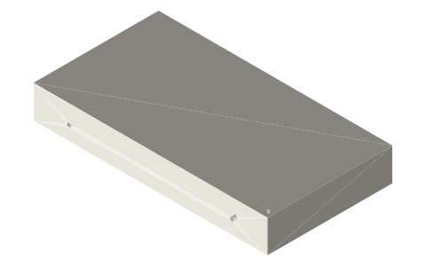
MEAN WELL LRS-350-12 power supply (case 207A): 215 × 115 × 30 case and M4 mounting holes
What are the MEAN WELL LRS-350-12 dimensions and mounting-hole positions? · Modern device · basis: MEAN WELL LRS-350 series specification, Mechanical Specification for case No. 207A.
Also called: LRS-350-12, MEAN WELL LRS-350, Meanwell LRS-350-12, LRS-350 case 207A, LRS-350 dimensions, 12 V 29 A power supply, LRS-350-24
Exact dimensions. Every file is drawn at true size with no tolerance added. The holes and pins that meet another part are listed below under Mating features, with the fit each joint needs; open those by your process's clearance before making the part. Mating features
- length
- 215.0 mm
- width
- 115.0 mm
- height
- 30.0 mm
Notes
- Datum: case centre; terminal-block end at −x, bottom at 0. Case 215.0 × 115.0 × 30.0 (case 207A, shared by the LRS-350 series).
- Bottom: 4 × M4 threaded holes, 3 mm thread length, on a 150.0 × 50.0 pattern centred on the case (32.5 from each end and each long edge).
- Sides: 2 × M4 threaded holes in each long side, 5 mm thread length, 150.0 apart, 12.5 above the bottom. All M4 holes are modelled at the Ø3.3 tap-drill size.
- The 9-position screw terminal (AC/L, AC/N, FG, 3 × −V, 3 × +V) sits recessed in the top of the −x end; the fan sits under a flush grille in the top, centred 47.45 from the +x end and 36.7 from the +y edge; air enters through the top.
- Not modelled: terminal block, fan grille and vent slots (all inside or flush with the case), optional mounting brackets.
- Dimensions are exact nominal (true size), no tolerance added.
MEAN WELL LRS-350-12 power supply (case 207A): 215 × 115 × 30 case… size chart
| holes | face | positions from case centre (mm) | thread |
|---|---|---|---|
| 4 | bottom | x ±75.0, y ±25.0 | M4, 3 mm deep |
| 2 | −y side | x ±75.0, 12.5 above bottom | M4, 5 mm deep |
| 2 | +y side | x ±75.0, 12.5 above bottom | M4, 5 mm deep |
Mating features
Drawn at the exact size. Open press, slide, run and socket features by your process's clearance (tolerances by process); leave designed gaps and clamp fits as drawn.
| feature | exact | mates with | fit | files |
|---|---|---|---|---|
| bottom M4 holes | 4 × M4 on 150.0 × 50.0, 3 mm thread | M4 screws through the mounting plate; screw may enter at most 3 mm | designed | all |
| side M4 holes | 2 × M4 per side, 150.0 apart, 12.5 up, 5 mm thread | M4 screws through an L-bracket or side wall; at most 5 mm into the case | designed | all |
Where the files are
Other publishers' files are linked, not hosted. "verify" = check the license at the link before commercial use.
| MEAN WELL | LRS-350 series specification | web | Publisher's page; dimensions are facts |
| MEAN WELL | LRS-350 product datasheet | web | Publisher's page; dimensions are facts |
Free files
★ Free files 1 parts. Generated by Xem Studio from the standard; threads are plain cylinders at major diameter. CC BY 4.0. index.json
| meanwell-lrs-350-12 | MEAN WELL LRS-350-12 power supply (case 207A): 215 × 115 × 30 case and M4 mounting holes | STEP · STL |
https://xemstudio.com/mcp to Claude, ChatGPT, Cursor or any MCP client (free, no account, one minute) and it can look up exact sizes, mating fits and free STEP/STL from every chat.Plain text: sheet.txt · JSON: /api/geometry?object=meanwell-lrs-350-12
Fits with
Questions
How big is the LRS-350-12?
215 × 115 × 30 mm (case 207A).
What is the bottom mounting-hole pattern?
Four M4 holes on 150 × 50 mm, centred on the case; thread length 3 mm, so the screw may enter at most 3 mm.
Can it be side-mounted?
Yes: two M4 holes in each long side, 150 mm apart and 12.5 mm above the bottom, 5 mm thread length.