 Xem Studiomeasured geometry
Library › Electronic components › Microcontroller boards ·
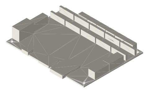
Makerbase MKS TinyBee V1.0 (ESP32 controller): 110 × 84 mm board, 4 mounting holes and connector heights
What are the MKS TinyBee V1.0 dimensions, mounting-hole pattern and connector clearances? · Modern device · basis: Makerbase 'MKS TinyBee V1.0_003 SIZE' drawing and the Makerbase TinyBee STEP model, both in the official makerbase-mks/MKS-TinyBee repository.
Also called: MKS TinyBee, mks tinybee, Makerbase MKS TinyBee V1.0, MKS TinyBee ESP32, TinyBee FluidNC board, MKS TinyBee mounting holes, MKS TinyBee size
Exact dimensions. Every file is drawn at true size with no tolerance added. The holes and pins that meet another part are listed below under Mating features, with the fit each joint needs; open those by your process's clearance before making the part. Mating features
- length
- 110.1 mm
- width
- 89.13 mm
- height
- 15.8 mm
Notes
- PCB 110.0 × 84.0, 1.6 thick, board bottom at 0. Power/heater terminals on one short edge, EXP1/EXP2 LCD headers on the other; USB, SD and the ESP32 antenna on one long edge, stepper connectors on the other.
- Four Ø3.2 mounting holes on a 102.0 × 76.0 rectangle, 4.0 in from each edge.
- Tallest part: the pluggable power terminal block, 15.8 above the board bottom; screw terminals 11.65, EXP headers 10.75, driver sockets and motor connectors 8.65.
- The SD card overhangs the board edge by 5.13 (89.13 overall), the micro-USB by 1.11 and the ESP32 antenna by 1.82.
- Not modelled: plug-in stepper driver modules and heatsinks (they add height above the driver sockets), capacitors, small 2-pin headers and pin tails under the board.
- All dimensions are exact nominal millimetres, true size, with no tolerance added.
Mating features
Drawn at the exact size. Open press, slide, run and socket features by your process's clearance (tolerances by process); leave designed gaps and clamp fits as drawn.
| feature | exact | mates with | fit | files |
|---|---|---|---|---|
| Mounting holes | 4 × Ø3.2 on 102.0 × 76.0 | M3 standoffs in an electronics enclosure | designed | all |
| Driver sockets | five pairs of 1×8 female rows, tops 8.65 above board bottom | plug-in StepStick drivers (A4988, DRV8825, TMC2209) | designed | all |
Where the files are
Other publishers' files are linked, not hosted. "verify" = check the license at the link before commercial use.
| Makerbase | MKS-TinyBee hardware files (size drawing and STEP) | web | Publisher's page; dimensions are facts |
| BDTronics | MKS TinyBee 32-bit 3D printer control board (ESP32) | web | Publisher's page; dimensions are facts |
Free files
★ Free files 1 parts. Generated by Xem Studio from the standard; threads are plain cylinders at major diameter. CC BY 4.0. index.json
| mks-tinybee-v1 | Makerbase MKS TinyBee V1.0 (ESP32 controller): 110 × 84 mm board, 4 mounting holes and connector heights | STEP · STL |
https://xemstudio.com/mcp to Claude, ChatGPT, Cursor or any MCP client (free, no account, one minute) and it can look up exact sizes, mating fits and free STEP/STL from every chat.Plain text: sheet.txt · JSON: /api/geometry?object=mks-tinybee-v1
Fits with
Questions
What is the MKS TinyBee hole pattern?
Four Ø3.2 holes on a 102 × 76 mm rectangle, 4 mm in from each edge of the 110 × 84 mm board.
How tall is the MKS TinyBee?
15.8 mm to the top of the power terminal block, without plug-in stepper drivers fitted.
Does anything stick out past the TinyBee board edge?
Yes: the SD card by 5.13 mm, the ESP32 antenna by 1.82 mm and the micro-USB by 1.11 mm.