 Xem Studiomeasured geometry
Library › Hardware › Bearings, rails & motion ·
O-ring groove dimensions, reciprocating (dynamic) gland, piston and rod, AS568
How deep and wide is the groove for an AS568 O-ring on a sliding piston or rod? · Standard part · basis: Parker O-Ring Handbook ORD 5700, Design Chart 5-2 (Industrial Reciprocating O-Ring Packing Glands), AS568 cross-sections .070 to .275 in
Also called: dynamic o-ring groove, o-ring groove dimensions piston, reciprocating o-ring gland, rod seal o-ring groove, o ring groove depth dynamic, o ring gland design, as568 -2xx groove, piston groove o-ring, o ring squeeze dynamic, hydraulic o-ring groove
Exact dimensions. True size, with no printing tolerance added.
- sizes
- 5 in table
Notes
- Depth L is the radial gland depth: the distance from the bore (piston seal) or the rod surface (rod seal) to the groove bottom. Piston gland: groove root Ø = bore Ø - 2L. Rod gland: groove root Ø = rod Ø + 2L. Widths G, G1, G2 are for no, one and two back-up rings.
- Squeeze, depth and clearance are tabulated as ranges because the O-ring, groove and bore each carry a tolerance. All figures are inches as printed; the sample files use the middle of each range, stated in the file notes.
- Reciprocating means a rod or piston slides through the ring: the squeeze is lower than static (about 8 to 25%) so the ring does not drag or heat. Widths, radii, diametral clearance and eccentricity are the same as for the static chart; only depth and squeeze change.
- The chart prints a surface finish of 32 RMS without a back-up ring and 63 RMS with one; corners are broken about .005 in radius, lead-in 0 to 5 degrees.
- Files: for each of the five cross-sections a piston-style sample ring (grooves in the outside) and a rod-style sample block (grooves in the bore), each carrying the three widths (no / 1 / 2 back-up) side by side, in true section at a sample diameter of 2.000 in. Groove-bottom corners are rounded at the middle of the printed radius range; the groove mouth is broken at the printed 0.005 in radius. Walls are square (the drawing's 0 to 5 degree draft is not modelled).
- Back-up rings themselves are not modelled, and nothing here is a tolerance or fit statement for your own machining or print process: add your process allowance.
O-ring groove dimensions, reciprocating (dynamic) gland, piston and… size chart
| AS568 series (dash sizes) | cross-section W, in | gland depth L, in | squeeze, in | squeeze, % | diametral clearance, in | groove width G, no back-up, in | G1, 1 back-up, in | G2, 2 back-ups, in | groove radius R, in | max eccentricity, in |
|---|---|---|---|---|---|---|---|---|---|---|
| -0xx (006 to 012) | 0.070 ± 0.003 | 0.055 to 0.057 | 0.010 to 0.018 | 15 to 25 | 0.002 to 0.005 | 0.093 to 0.098 | 0.138 to 0.143 | 0.205 to 0.210 | 0.005 to 0.015 | 0.002 |
| -1xx (104 to 116) | 0.103 ± 0.003 | 0.088 to 0.090 | 0.010 to 0.018 | 10 to 17 | 0.002 to 0.005 | 0.140 to 0.145 | 0.171 to 0.176 | 0.238 to 0.243 | 0.005 to 0.015 | 0.002 |
| -2xx (201 to 222) | 0.139 ± 0.004 | 0.121 to 0.123 | 0.012 to 0.022 | 9 to 16 | 0.003 to 0.006 | 0.187 to 0.192 | 0.208 to 0.213 | 0.275 to 0.280 | 0.010 to 0.025 | 0.003 |
| -3xx (309 to 349) | 0.210 ± 0.005 | 0.185 to 0.188 | 0.017 to 0.030 | 8 to 14 | 0.003 to 0.006 | 0.281 to 0.286 | 0.311 to 0.316 | 0.410 to 0.415 | 0.020 to 0.035 | 0.004 |
| -4xx (425 to 460) | 0.275 ± 0.006 | 0.237 to 0.240 | 0.029 to 0.044 | 11 to 16 | 0.004 to 0.007 | 0.375 to 0.380 | 0.408 to 0.413 | 0.538 to 0.543 | 0.020 to 0.035 | 0.005 |
Where the files are
Other publishers' files are linked, not hosted. "verify" = check the license at the link before commercial use.
| Parker Hannifin O-Ring Division (chart as copied by All Seals Inc.) | Parker O-Ring Handbook ORD 5700, Design Chart 5-2: Industrial Reciprocating O-Ring Packing Glands | web | Publisher's page; dimensions are facts |
| Parker Hannifin O-Ring Division | Parker O-Ring Handbook ORD 5700 (full handbook, Sections IV and V: static and dynamic O-ring sealing) | web | Publisher's page; dimensions are facts |
Free files
★ Free files 10 parts. Generated by Xem Studio from the standard; threads are plain cylinders at major diameter. CC BY 4.0. index.json
| gland-dynamic-piston-sample-cs070 | -0xx series, cross-section 0.070 in: gland depth 0.0560 in, groove-bottom radius 0.0100 in, mouth edge break 0.005 in, widths no / 1 / 2 back-up ring 0.0955 / 0.1405 / 0.2075 in. Piston-style sample ring (grooves in the outside): bore 2.000 in, piston Ø 1.9965 in (bore less the mid diametral clearance 0.0035 in), hole Ø 1.000 in, 0.200 in lands. Middle of each printed range; the layout is a sample, not a standard. | STEP · STL |
| gland-dynamic-rod-sample-cs070 | -0xx series, cross-section 0.070 in: gland depth 0.0560 in, groove-bottom radius 0.0100 in, mouth edge break 0.005 in, widths no / 1 / 2 back-up ring 0.0955 / 0.1405 / 0.2075 in. Rod-style sample block (grooves in the bore): rod Ø 2.000 in, housing bore Ø 2.0035 in (rod plus the mid diametral clearance), groove root Ø 2.1120 in, 0.200 in lands, 0.500 in wall outside the root. Middle of each printed range; the layout is a sample, not a standard. | STEP · STL |
| gland-dynamic-piston-sample-cs103 | -1xx series, cross-section 0.103 in: gland depth 0.0890 in, groove-bottom radius 0.0100 in, mouth edge break 0.005 in, widths no / 1 / 2 back-up ring 0.1425 / 0.1735 / 0.2405 in. Piston-style sample ring (grooves in the outside): bore 2.000 in, piston Ø 1.9965 in (bore less the mid diametral clearance 0.0035 in), hole Ø 1.000 in, 0.200 in lands. Middle of each printed range; the layout is a sample, not a standard. | STEP · STL |
| gland-dynamic-rod-sample-cs103 | -1xx series, cross-section 0.103 in: gland depth 0.0890 in, groove-bottom radius 0.0100 in, mouth edge break 0.005 in, widths no / 1 / 2 back-up ring 0.1425 / 0.1735 / 0.2405 in. Rod-style sample block (grooves in the bore): rod Ø 2.000 in, housing bore Ø 2.0035 in (rod plus the mid diametral clearance), groove root Ø 2.1780 in, 0.200 in lands, 0.500 in wall outside the root. Middle of each printed range; the layout is a sample, not a standard. | STEP · STL |
| gland-dynamic-piston-sample-cs139 | -2xx series, cross-section 0.139 in: gland depth 0.1220 in, groove-bottom radius 0.0175 in, mouth edge break 0.005 in, widths no / 1 / 2 back-up ring 0.1895 / 0.2105 / 0.2775 in. Piston-style sample ring (grooves in the outside): bore 2.000 in, piston Ø 1.9955 in (bore less the mid diametral clearance 0.0045 in), hole Ø 1.000 in, 0.200 in lands. Middle of each printed range; the layout is a sample, not a standard. | STEP · STL |
| gland-dynamic-rod-sample-cs139 | -2xx series, cross-section 0.139 in: gland depth 0.1220 in, groove-bottom radius 0.0175 in, mouth edge break 0.005 in, widths no / 1 / 2 back-up ring 0.1895 / 0.2105 / 0.2775 in. Rod-style sample block (grooves in the bore): rod Ø 2.000 in, housing bore Ø 2.0045 in (rod plus the mid diametral clearance), groove root Ø 2.2440 in, 0.200 in lands, 0.500 in wall outside the root. Middle of each printed range; the layout is a sample, not a standard. | STEP · STL |
| gland-dynamic-piston-sample-cs210 | -3xx series, cross-section 0.210 in: gland depth 0.1865 in, groove-bottom radius 0.0275 in, mouth edge break 0.005 in, widths no / 1 / 2 back-up ring 0.2835 / 0.3135 / 0.4125 in. Piston-style sample ring (grooves in the outside): bore 2.000 in, piston Ø 1.9955 in (bore less the mid diametral clearance 0.0045 in), hole Ø 1.000 in, 0.200 in lands. Middle of each printed range; the layout is a sample, not a standard. | STEP · STL |
| gland-dynamic-rod-sample-cs210 | -3xx series, cross-section 0.210 in: gland depth 0.1865 in, groove-bottom radius 0.0275 in, mouth edge break 0.005 in, widths no / 1 / 2 back-up ring 0.2835 / 0.3135 / 0.4125 in. Rod-style sample block (grooves in the bore): rod Ø 2.000 in, housing bore Ø 2.0045 in (rod plus the mid diametral clearance), groove root Ø 2.3730 in, 0.200 in lands, 0.500 in wall outside the root. Middle of each printed range; the layout is a sample, not a standard. | STEP · STL |
| gland-dynamic-piston-sample-cs275 | -4xx series, cross-section 0.275 in: gland depth 0.2385 in, groove-bottom radius 0.0275 in, mouth edge break 0.005 in, widths no / 1 / 2 back-up ring 0.3775 / 0.4105 / 0.5405 in. Piston-style sample ring (grooves in the outside): bore 2.000 in, piston Ø 1.9945 in (bore less the mid diametral clearance 0.0055 in), hole Ø 1.000 in, 0.200 in lands. Middle of each printed range; the layout is a sample, not a standard. | STEP · STL |
| gland-dynamic-rod-sample-cs275 | -4xx series, cross-section 0.275 in: gland depth 0.2385 in, groove-bottom radius 0.0275 in, mouth edge break 0.005 in, widths no / 1 / 2 back-up ring 0.3775 / 0.4105 / 0.5405 in. Rod-style sample block (grooves in the bore): rod Ø 2.000 in, housing bore Ø 2.0055 in (rod plus the mid diametral clearance), groove root Ø 2.4770 in, 0.200 in lands, 0.500 in wall outside the root. Middle of each printed range; the layout is a sample, not a standard. | STEP · STL |
https://xemstudio.com/mcp to Claude, ChatGPT, Cursor or any MCP client (free, no account, one minute) and it can look up exact sizes, mating fits and free STEP/STL from every chat.Plain text: sheet.txt · JSON: /api/geometry?object=oring-gland-dynamic-reciprocating-as568
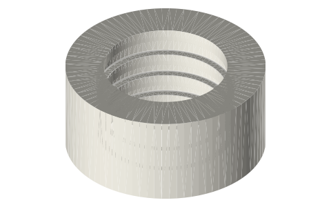
Fits with
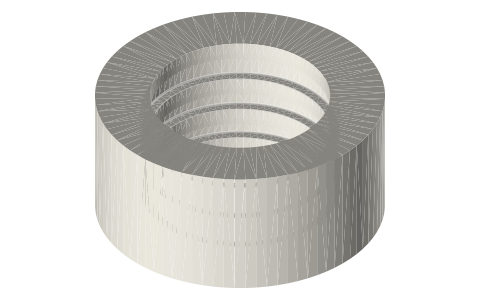
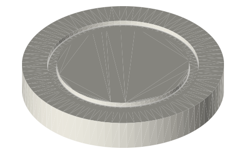
Questions
How deep is the groove for a -2xx O-ring on a moving piston?
L = .121 to .123 in (squeeze .012 to .022 in, 9 to 16%); groove .187 to .192 in wide with no back-up ring.
What is the maximum eccentricity for a -3xx dynamic gland?
.004 in (cross-section .210 in); diametral clearance .003 to .006 in.
Why is a dynamic groove shallower to the O-ring than a static one?
The chart sets less squeeze for a sliding seal: e.g. -2xx static squeeze 16 to 23% against 9 to 16% reciprocating, so the groove is about .010 in deeper.