 Xem Studiomeasured geometry
Clevis pins, R-clips, cotter pins, clevises, universal joint, rod ends (heim joints)
What size clevis pin and R-clip for a 3D printed linkage? · Hardware · basis: ISO 2341 clevis pins, DIN 11024 R-clips, common rod-end (POS/PHS series) ball sizes; printed clevises and a universal joint sized to Ø3/Ø5 pins
Long Earth Society build part. Serviceable pivots on the LES linkages; a U-joint between engine and alternator when the shafts don't line up. The engines · all LES parts
- sizes
- 6 in table
Notes
- Clevis pin: plain shank with a head and a cross-hole; Ø3 × 12–20, Ø5 × 20–30, Ø8 × 40 cover model work. Printed hole Ø+0.2 for a pivot, Ø−0.05 press in the fixed side. R-clip (hairpin) sizes by pin: 2–3 mm pin → size 2; 4–5 → size 3–4; 6–8 → size 5. Cotter pins (split pins) Ø1.6 × 16 and Ø2 × 20 for the same holes.
- Clevis: fork with a pin across the gap; gap = link thickness + 0.4. The printed ones take an M3 pushrod in the shank. A clevis + pin + R-clip is the field-serviceable joint: no tools.
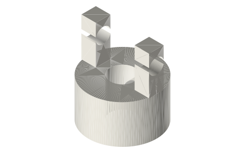
- Universal joint: two yokes and a cross spider on Ø3 pins; transmits rotation across up to 25° with velocity ripple (use two, phased, for constant velocity). Ø14 printed yokes on Ø5 shafts.
- Rod ends (heim joints): M3 (ball Ø6), M4 (Ø8), M5 (Ø10), M6 (Ø12), M8 (Ø16) threaded shank, ±13° misalignment; the envelopes here are for fit; buy the steel part (POSA/PHSA series). Male on the rod, female (PHS) takes a bolt through the ball.
Sizes
| part | sizes | mating hole | note |
|---|---|---|---|
| clevis pin | Ø3, 4, 5, 6, 8 × 12–40 | Ø + 0.2 pivot / − 0.05 press | ISO 2341 |
| R-clip | sizes 2–5 | cross-hole Ø1–1.6 | DIN 11024 |
| cotter pin | Ø1.6 × 16, Ø2 × 20 | Ø1.8 / 2.2 | ISO 1234 |
| clevis (printed) | Ø3 pin gap 5/8, Ø5 gap 8/10, Ø6 gap 12 | M3 shank | — |
| universal joint | Ø14 yokes, Ø5 shafts | Ø3 cross pins | 25° max |
| rod end | M3–M8, ball Ø6–16 | bolt through ball | POS/PHS series |
Where the files are
Other publishers' files are linked, not hosted. "verify" = check the license at the link before commercial use.
| Wikipedia | Clevis fastener | web | CC BY-SA 4.0 (text) |
| Wikipedia | Universal joint | web | CC BY-SA 4.0 (text) |
| Wikipedia | Rod end bearing | web | CC BY-SA 4.0 (text) |
| McMaster-Carr | Clevis pins (free STEP per part, for your own design use; no redistribution) | STEP, PDF | McMaster-Carr site terms verify |
| McMaster-Carr | Rod ends (free STEP per part, for your own design use; no redistribution) | STEP, PDF | McMaster-Carr site terms verify |
| Long Earth Society | Engine and rig builds | web, video | LES site |
Free files
★ Free files 23 parts. Generated by Xem Studio from the standard; threads are plain cylinders at major diameter. CC BY 4.0. index.json
| clevis-pin-3x12 | clevis pin Ø3 × 12 with head and cross-hole for an R-clip | STEP · STL |
| clevis-pin-3x20 | clevis pin Ø3 × 20 with head and cross-hole for an R-clip | STEP · STL |
| clevis-pin-4x20 | clevis pin Ø4 × 20 with head and cross-hole for an R-clip | STEP · STL |
| clevis-pin-5x20 | clevis pin Ø5 × 20 with head and cross-hole for an R-clip | STEP · STL |
| clevis-pin-5x30 | clevis pin Ø5 × 30 with head and cross-hole for an R-clip | STEP · STL |
| clevis-pin-6x30 | clevis pin Ø6 × 30 with head and cross-hole for an R-clip | STEP · STL |
| clevis-pin-8x40 | clevis pin Ø8 × 40 with head and cross-hole for an R-clip | STEP · STL |
| r-clip-2 | R-clip (hairpin cotter) for a Ø2–3 pin | STEP · STL |
| r-clip-3 | R-clip (hairpin cotter) for a Ø3–4 pin | STEP · STL |
| r-clip-4 | R-clip (hairpin cotter) for a Ø4–5 pin | STEP · STL |
| r-clip-5 | R-clip (hairpin cotter) for a Ø5–6 pin | STEP · STL |
| clevis-3-gap5 | printed clevis for a Ø3 pin, 5 mm gap, M3 rod | STEP · STL |
| clevis-3-gap8 | printed clevis for a Ø3 pin, 8 mm gap, M3 rod | STEP · STL |
| clevis-5-gap8 | printed clevis for a Ø5 pin, 8 mm gap, M3 rod | STEP · STL |
| clevis-5-gap10 | printed clevis for a Ø5 pin, 10 mm gap, M3 rod | STEP · STL |
| clevis-6-gap12 | printed clevis for a Ø6 pin, 12 mm gap, M3 rod | STEP · STL |
| ujoint-yoke-5mm | universal joint yoke Ø14, Ø5 bore, Ø3 cross pins (print two) | STEP · STL |
| ujoint-spider-14 | universal joint spider for the Ø14 yokes, Ø3 pins | STEP · STL |
| rod-end-m3 | rod end (heim joint) envelope M3: ball bore 3, ball Ø6, head OD +4 | STEP · STL |
| rod-end-m4 | rod end (heim joint) envelope M4: ball bore 4, ball Ø8, head OD +4 | STEP · STL |
| rod-end-m5 | rod end (heim joint) envelope M5: ball bore 5, ball Ø10, head OD +4 | STEP · STL |
| rod-end-m6 | rod end (heim joint) envelope M6: ball bore 6, ball Ø12, head OD +4 | STEP · STL |
| rod-end-m8 | rod end (heim joint) envelope M8: ball bore 8, ball Ø16, head OD +4 | STEP · STL |
Plain text: sheet.txt · JSON: /api/geometry?object=pins-clevises-and-joints
Fits with
Questions
What clevis pin size for a model linkage?
Ø3 mm pins (with size-2 R-clips) for printed links up to 10 mm thick; Ø5 for anything carrying a flywheel load. Pivot holes at Ø3.2 / Ø5.2.
What are M5 rod end dimensions?
Ball bore 5 mm, ball Ø10, head about Ø14 × 8 mm thick, M5 shank 20 mm; ±13° of misalignment.
How much angle can a universal joint take?
Single joint: 25° with speed ripple; two joints with parallel yokes cancel the ripple (constant velocity) at the same angle.