 Xem Studiomeasured geometry
Library › 3D printing › Print-in-place mechanisms ·
Print-in-place: crank-and-slider linkage with captive pins
How do you 3D print a working crank and slider in one piece? · Hardware · basis: Xem Studio design: offset slider-crank, captive square pins with 45° heads; one designed running gap of 0.40 mm
Also called: print in place crank slider, print in place linkage, 3d printed slider crank, piston crank mechanism stl, print in place pin joint
Exact dimensions. True size, with no printing tolerance added.
- length
- 109.0 mm
- width
- 32.8 mm
- height
- 31.0 mm
Notes
- 3D print in place — prints already assembled, moving, in one job. Drawn at true size with no printer tolerance added; the 0.40 mm running gaps are part of the design.
- Running gap 0.40 mm per side, 0.80 mm on diameter — part of the design, drawn as is. On the 45° faces the same 0.40 mm is measured square to the face (0.57 mm along the axis).
- Bed: the linkage stands on edge, its plane vertical: the frame plate with its foot, then the crank, the rod and the slider in three 6 mm layers side by side, 0.40 mm apart. The crank is drawn pointing straight down and the rod lies flat, so all four bodies reach the bed (crank and rod ends on 45° feet).
- Support while printing: every pin is a square bar standing on its corner (45° faces), cantilevered from its plate, ending in a 45° conical head trimmed underneath to the bar's own 45° V so that it grows from the bar; every bore is round with a 45° peaked roof and a 45° countersink for the head. The slider rides a 45° V-ridge on the frame plate.
- Captured: each pin's head reaches past its bore (Ø5.2) into the countersink of the next plate at every angle, so no plate can slide off its pin; the slider is held up and down by the V-ridge in its V-groove and sideways between the frame plate and the rod.
- Freeing it: hold the frame and turn the crank slowly a full turn, then a few more; the slider runs back and forth on its own.
- Motion: the crank turns 360° continuously; the slider strokes 31.1 mm (offset slider-crank, quick-return 188° : 172°). The whole turn was checked in the model every 15° with no contact.
Print-in-place: crank-and-slider linkage with captive pins size chart
| key | value | what |
|---|---|---|
| gap_mm | 0.4 | running gap per side on every moving interface (radial, axial, under captured parts) — part of the design, not a tolerance |
| crank_r_mm | 15.0 | throw |
| rod_l_mm | 60.0 | connecting rod, centre to centre |
| offset_mm | 15.0 | slide line below the crank pivot |
| stroke_mm | 31.06 | slider travel per crank turn (computed) |
| quick_return | 1.093 | crank angle forward : back = 188° : 172° |
| pin_d_mm | 4.4 | captive pins: square section on its corner (sweeps Ø4.4), 45° conical head up to Ø8.4 (upper part, above the bar's 45° V) |
| bore_d_mm | 5.2 | pin bores, 45° peaked roof |
| plate_t_mm | 6 | crank, rod and slider, each |
| pivot_h_mm | 22.0 | crank pivot above the bed |
| rotation_deg | 360 continuous | crank |
| frame_l_mm | 109.0 | |
| mount_holes | 3 × Ø4.5 | frame foot |
Where the files are
Other publishers' files are linked, not hosted. "verify" = check the license at the link before commercial use.
| Xem Studio | Print-in-place mechanism design (geometry computed in the generator) | web | Xem Studio design |
Free files
★ Free files 5 parts. Xem Studio design: free to use, print and sell things from; not to be republished as files. Xem Studio Design License. index.json
| print-in-place-crank-slider-assembly | The whole print as laid on the bed (4 bodies, already assembled); STEP keeps each moving body a separate solid | STEP · STL |
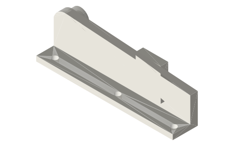
| print-in-place-crank-slider-frame | Frame plate with foot, crank pivot pin and the 45° V-ridge rail | STEP · STL |
| print-in-place-crank-slider-crank | Crank, 15 mm throw, with its crank pin | STEP · STL |
| print-in-place-crank-slider-rod | Connecting rod, 60 mm centres | STEP · STL |
| print-in-place-crank-slider-slider | Slider on the V-ridge, with its pin | STEP · STL |
https://xemstudio.com/mcp to Claude, ChatGPT, Cursor or any MCP client (free, no account, one minute) and it can look up exact sizes, mating fits and free STEP/STL from every chat.Plain text: sheet.txt · JSON: /api/geometry?object=print-in-place-crank-slider
Fits with
Questions
Why are the pins square?
A square bar standing on its corner has only 45° faces, so it prints cantilevered without support; its corners sweep a Ø4.4 circle that turns in a Ø5.2 bore.
What is the stroke?
31.1 mm: the slider line is 15 mm below the crank pivot (an offset slider-crank), so the stroke is a little more than twice the 15 mm throw and the return is quicker than the forward run.