 Xem Studiomeasured geometry
Library › 3D printing › Print-in-place mechanisms ·
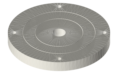
Print-in-place: two-axis gimbal (nested rings, Ø76)
How do you 3D print a gimbal (universal pivot) in one piece? · Hardware · basis: Xem Studio design: concentric sphere bands, 45° cone pivots; one designed running gap of 0.40 mm
Also called: print in place gimbal, 3d printed gimbal rings, print in place universal joint, gyroscope rings stl, nested rings gimbal
Exact dimensions. True size, with no printing tolerance added.
- length
- 76.0 mm
- width
- 76.0 mm
- height
- 8.0 mm
Notes
- 3D print in place — prints already assembled, moving, in one job. Drawn at true size with no printer tolerance added; the 0.40 mm running gaps are part of the design.
- Running gap 0.40 mm per side, 0.80 mm on diameter — part of the design, drawn as is. On the 45° faces the same 0.40 mm is measured square to the face (0.57 mm along the axis).
- Bed: all three rings lie flat and concentric on the bed; the two pivot axes (X and Y) are horizontal at mid-height, 4 mm up.
- Support while printing: the facing edges are concentric sphere bands (the inner one only 13° off vertical at the bed), and each pivot is a 45° cone on a horizontal axis in a 45° cone socket; nothing overhangs more than 45°.
- Captured: each ring hangs on two opposed cones, so it cannot drop out; the sphere bands keep the 0.40 mm gap at every angle.
- Freeing it: hold the frame and turn the middle ring through a full turn, then the inner disc; the first turn breaks the bed contact.
- Motion: the middle ring turns 360° about X and the disc 360° about Y — checked in the model every 30° × 45° with no contact; together they point the disc in any direction (two-axis gimbal).
Print-in-place: two-axis gimbal size chart
| key | value | what |
|---|---|---|
| gap_mm | 0.4 | running gap per side on every moving interface (radial, axial, under captured parts) — part of the design, not a tolerance |
| outer_d_mm | 76.0 | frame ring outside diameter |
| h_mm | 8.0 | all three rings, as printed |
| ring_1_sphere_d_mm | 54.0 | middle ring outer sphere band |
| disc_sphere_d_mm | 36.0 | inner disc sphere band |
| pin_d_mm | 5.2 | 45° cone pivots, two per axis |
| center_hole_d_mm | 10 | inner disc |
| rotation_x_deg | 360 continuous | middle ring in the frame |
| rotation_y_deg | 360 continuous | inner disc in the middle ring |
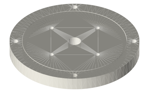
| mount_holes | 4 × Ø3.4 on Ø67 | frame |
Where the files are
Other publishers' files are linked, not hosted. "verify" = check the license at the link before commercial use.
| Xem Studio | Print-in-place mechanism design (geometry computed in the generator) | web | Xem Studio design |
Free files
★ Free files 4 parts. Xem Studio design: free to use, print and sell things from; not to be republished as files. Xem Studio Design License. index.json
| print-in-place-two-axis-gimbal-assembly | The whole print as laid on the bed (3 bodies, already assembled); STEP keeps each moving body a separate solid | STEP · STL |
| print-in-place-two-axis-gimbal-frame | Frame ring Ø76 × 8 with the X-axis cone sockets and 4 × Ø3.4 | STEP · STL |
| print-in-place-two-axis-gimbal-ring | Middle ring: sphere bands inside and out, X-axis cones, Y-axis sockets | STEP · STL |
| print-in-place-two-axis-gimbal-disc | Inner disc: sphere band Ø36, Y-axis cones, Ø10 centre hole | STEP · STL |
https://xemstudio.com/mcp to Claude, ChatGPT, Cursor or any MCP client (free, no account, one minute) and it can look up exact sizes, mating fits and free STEP/STL from every chat.Plain text: sheet.txt · JSON: /api/geometry?object=print-in-place-two-axis-gimbal
Fits with
Questions
Why are the ring edges spherical?
A sphere band keeps the same 0.40 mm gap to the next ring at every tilt; flat-sided rings would jam after a few degrees.
What are the pivots?
45° cones Ø5.2 at the base on each ring, two per axis, running in 45° cone sockets of the next ring out.