 Xem Studiomeasured geometry
Library › Stirling engines › Drives & mechanisms ·
Rhombic drive kit (Philips beta Stirling): twin crank gears, links, yokes, frame
How does a rhombic drive Stirling engine work and what parts does it need? · Hardware · basis: Philips/Meijer rhombic drive: two counter-rotating crank gears, four equal links, two yokes; displacer rod through the piston; geometry here e = 8, link 40, gear centres 32 (module 1, 30 T), scaled for a 2 in tri-clamp beta
Long Earth Society build part. The balanced beta drive for the 2 in tri-clamp engine. The engines
- sizes
- 7 in table
Notes
- The rhombic drive is the classic beta mechanism (Philips 1950s): two identical gears mesh and turn opposite ways, each carrying a crank pin; four equal links join the pins to an upper yoke (displacer rod) and a lower yoke (piston rod, a tube the displacer rod runs through). Because the two cranks are mirror images every side load cancels: the piston and displacer move on the axis with no piston slap, perfectly balanced, and the phase angle is fixed by the geometry (about 90° for these proportions).
- Geometry rules: gear centre distance c, crank throw e, link length L. Stroke ≈ 2e for both yokes; the displacer leads the piston by an angle set by c/L and e/L (Meijer's charts); with c = 32, e = 8, L = 40 you get ~85–95° and strokes of 16 mm. Keep L ≥ 4e. Gears must be meshed with the pins 180° apart (one at top dead centre when the other is at bottom): mark a tooth.
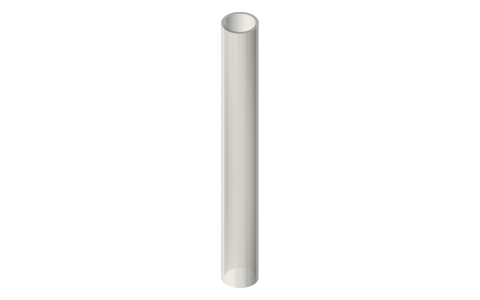
- Parts: 2 crank gears (module 1 30 T, Ø5 shafts in 623 bearings in the frame plates), 4 links (40 mm, Ø3 pins), upper yoke (Ø3 displacer rod clamp), lower yoke (Ø5 tube piston rod, Ø3.6 clearance for the displacer rod), 2 frame plates, 4 Ø3 crank pins. Rod tube: 5 mm K&S brass (3.1 ID) is the piston rod with the Ø3 displacer rod inside.
- LES: the 2 in beta on the rhombic drive is the balanced, quiet one; matches the Ø46 × 90 tri-clamp displacer at 16 mm stroke, with the syringe or a lapped Ø20 power piston.
Sizes
| parameter | value_mm | note |
|---|---|---|
| gear centres c | 32 | 30 T module 1 gears |
| crank throw e | 8 | stroke 16 |
| link length L | 40 | ≥ 4e |
| yoke span | 32 | = c at mid-stroke |
| displacer rod | Ø3 | through Ø5 tube |
| piston rod | Ø5 tube (3.1 ID) | K&S brass |
| bearings | 4 × 623 | frame plates |
Where the files are
Other publishers' files are linked, not hosted. "verify" = check the license at the link before commercial use.
| Wikipedia | Rhombic drive | web | CC BY-SA 4.0 (text) |
| Wikipedia | Stirling engine | web | CC BY-SA 4.0 (text) |
| Philips Research / Meijer | The Philips Stirling engine (rhombic drive papers, 1958–1965) | web | reference verify |
| Long Earth Society | Engine builds | web, video | LES site |
Free files
★ Free files 10 parts. Generated by Xem Studio from the standard; threads are plain cylinders at major diameter. CC BY 4.0. index.json
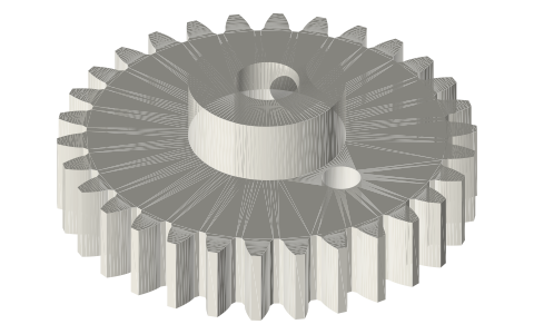
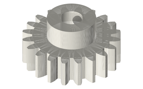
| crank-gear-30t-e8-left | crank gear 30 T module 1, Ø5 bore hub, Ø3 crank pin at 8.0 mm (stroke 16.0); left (identical; mesh them 180° apart) | STEP · STL |
| crank-gear-30t-e8-right | crank gear 30 T module 1, Ø5 bore hub, Ø3 crank pin at 8.0 mm (stroke 16.0); right (identical; mesh them 180° apart) | STEP · STL |
| link-40-1 | rhombic link 40.0 mm centres, Ø3.2 pivots (4 needed) | STEP · STL |
| link-40-2 | rhombic link 40.0 mm centres, Ø3.2 pivots (4 needed) | STEP · STL |
| link-40-3 | rhombic link 40.0 mm centres, Ø3.2 pivots (4 needed) | STEP · STL |
| link-40-4 | rhombic link 40.0 mm centres, Ø3.2 pivots (4 needed) | STEP · STL |
| yoke-upper-displacer | upper yoke (displacer rod Ø3) span 32 mm pivots | STEP · STL |
| yoke-lower-piston | lower yoke (piston on a Ø5 tube rod, displacer Ø3 rod passes through) span 32 | STEP · STL |
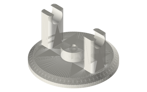
| gear-frame-plate-c32 | frame plate with Ø10.2 pockets for 623 bearings on 32 mm centres and a Ø16 rod clearance (print two) | STEP · STL |
| crank-pin-3x14 | Ø3 × 14 crank pin (dowel) for the gears | STEP · STL |
Plain text: sheet.txt · JSON: /api/geometry?object=rhombic-drive-kit
Fits with
Questions
What is a rhombic drive?
Two counter-rotating crank gears and four links forming a rhombus between two yokes; the top yoke drives the displacer, the bottom yoke the piston, both on one axis. Fully balanced, no side load, fixed phase angle.
How do I set the phase angle on a rhombic drive?
It is built into the geometry (gear spacing, throw and link length) and the 180° meshing of the gears; with c 32 / e 8 / L 40 it is about 90°. Change e/L to adjust.
What stroke does this rhombic kit give?
16 mm for both displacer and piston (2 × 8 mm throw); scale e and L together for other strokes, keeping L ≥ 4e and c ≈ 4e.