 Xem Studiomeasured geometry
Library › Stirling engines › Tri-clamp engine parts ·
Tri-clamp displacers and engine heads: 1.5, 2 and 3 in spools
What size displacer fits a 2 inch tri-clamp spool and what caps do I need to make it a Stirling engine? · Hardware · basis: 16 ga ASME BPE tube bores (1.5 in = 34.8 mm, 2 in = 47.5, 3 in = 72.9) from the tri-clamp spool entry; displacer radial gap 0.6–1.0 mm for low-ΔT air engines (Senft); ISO 2852 cap face from the tri-clamp end cap entry
Long Earth Society build part. The displacers and heads the LES tri-clamp engines are built from. The engines · all LES parts
- sizes
- 9 in table
Notes
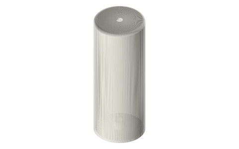
- Displacer diameter = bore − 2 × gap: 1.5 in → Ø33.6, 2 in → Ø46.0, 3 in → Ø70.9. Length 1.5–2.5 × bore (the longer, the bigger the temperature difference it can hold across itself); stroke 0.3–0.4 × length. A 2 in × 6 in spool takes the Ø46 × 90 displacer with a 30 mm stroke.
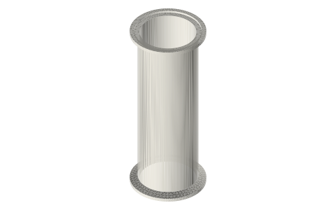
- Shell displacers: 1 mm wall, closed hot end, internal rings every 25 mm, printed open end up (no supports); the cap presses in and carries the Ø3 rod on an M3 grub. Mass matters less than you think at 2–5 Hz; stiffness and straightness matter more. PETG for a cold end under 80 °C; the hot end of the displacer sees the hot plate only by radiation: PETG survives a tea-light engine, use a foam-and-foil or a thin stainless cup over the nose for a burner engine.
- Regenerative (annular-gap) displacer: 1.5 mm gap and 12 slots packed with #100 stainless mesh turn the gap into the regenerator (Senft's LTD trick); use it in a single spool with no separate regenerator section. Foam templates: cut closed-cell foam (EVA, pool noodle) to Ø and length with the cross lines for centring the rod.
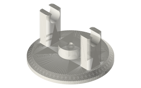
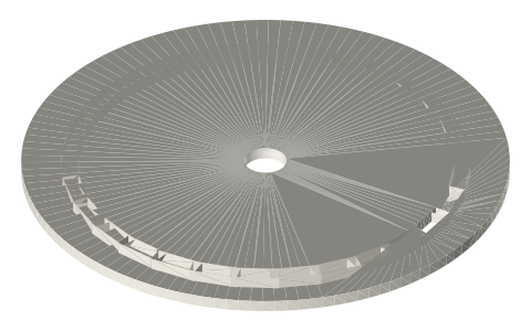
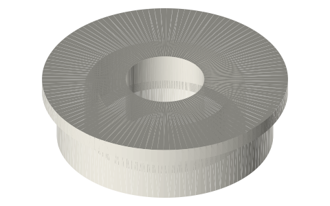
- Heads (ISO 2852 caps with features on the back, so a stock clamp and gasket seal them): displacer head (3/32 in brass guide tube press-fit on centre + 4 mm barb), power head (10 mL syringe barrel socket, Ø15.9, as the power cylinder + M5 port), instrument head (DS18B20, K-type and a barb), crank head (Ø3 rod gland with an O-ring groove and two 623 towers 24 mm up for a crankshaft right on the cap). Heads print flat, face down, at 0.15 mm layers; sand the sealing land.
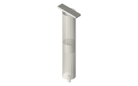
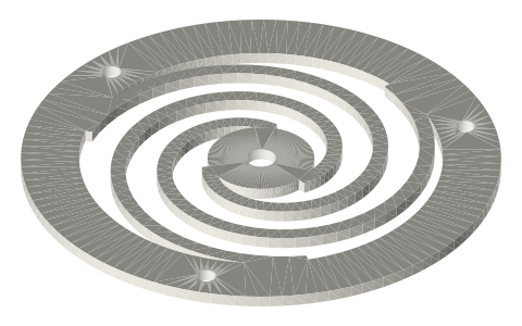
- Engine recipes: Gamma, 2 in: hot ferrule + 6 in spool + displacer head on top, Ø46 × 90 shell displacer, power head with a 10 mL syringe on a side tee or the crank head; flywheel Ø100 on the crank kit. Beta: one spool, regenerative displacer, crank head on the cold end. Free-piston: 2 in spool, Ø46 displacer on the spiral flexures, power piston from the free-piston core.
- LES: this is the shelf the LES engines are literally built from; every head here replaces a flat cap that used to be drilled by hand.
Sizes
| spool | bore_mm | displacer_od_mm | length_mm | radial_gap_mm | type |
|---|---|---|---|---|---|
| 1.5 | 34.800000000000004 | 33.6 | 50 | 0.6 | shell / foam |
| 1.5 | 34.800000000000004 | 33.6 | 75 | 0.6 | shell / foam |
| 1.5 | 34.800000000000004 | 33.6 | 100 | 0.6 | shell / foam |
| 2 | 47.5 | 46.0 | 60 | 0.75 | shell / foam |
| 2 | 47.5 | 46.0 | 90 | 0.75 | shell / foam |
| 2 | 47.5 | 46.0 | 120 | 0.75 | shell / foam |
| 3 | 72.9 | 70.9 | 80 | 1.0 | shell / foam |
| 3 | 72.9 | 70.9 | 120 | 1.0 | shell / foam |
| 3 | 72.9 | 70.9 | 160 | 1.0 | shell / foam |
Where the files are
Other publishers' files are linked, not hosted. "verify" = check the license at the link before commercial use.
| Long Earth Society | Tri-clamp Stirling engine builds | web, video | LES site |
| James R. Senft | An Introduction to Low Temperature Differential Stirling Engines (displacer and gap design) | book | Moriya Press verify |
| Wikipedia | Stirling engine | web | CC BY-SA 4.0 (text) |
Free files
★ Free files 46 parts. Generated by Xem Studio from the standard; threads are plain cylinders at major diameter. CC BY 4.0. index.json
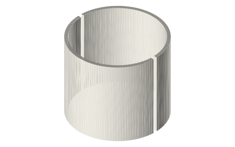
| displacer-shell-1.5in-50 | 1.5 in shell displacer Ø33.6 × 50 for the Ø34.8 bore (0.6 mm radial gap), 1 mm wall, ribbed; print open end up, 0.8 mm nozzle-friendly | STEP · STL |
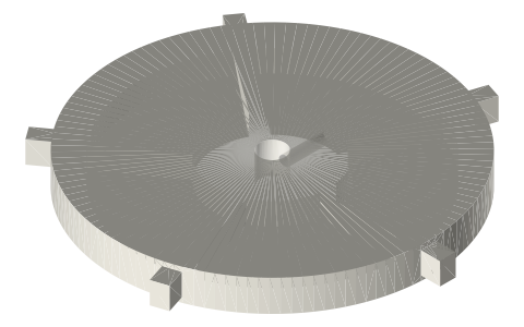
| displacer-cap-1.5in | 1.5 in displacer end cap with Ø3 rod boss and M3 grub (print one per displacer) | STEP · STL |
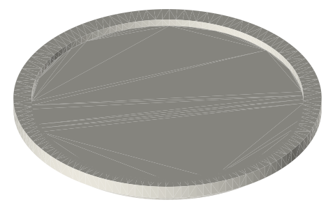
| displacer-foam-template-1.5in-50 | 1.5 in foam displacer cutting template Ø33.6 × 50 with centre and cross lines | STEP · STL |
| displacer-shell-1.5in-75 | 1.5 in shell displacer Ø33.6 × 75 for the Ø34.8 bore (0.6 mm radial gap), 1 mm wall, ribbed; print open end up, 0.8 mm nozzle-friendly | STEP · STL |
| displacer-cap-1.5in | 1.5 in displacer end cap with Ø3 rod boss and M3 grub (print one per displacer) | STEP · STL |
| displacer-foam-template-1.5in-75 | 1.5 in foam displacer cutting template Ø33.6 × 75 with centre and cross lines | STEP · STL |
| displacer-shell-1.5in-100 | 1.5 in shell displacer Ø33.6 × 100 for the Ø34.8 bore (0.6 mm radial gap), 1 mm wall, ribbed; print open end up, 0.8 mm nozzle-friendly | STEP · STL |
| displacer-cap-1.5in | 1.5 in displacer end cap with Ø3 rod boss and M3 grub (print one per displacer) | STEP · STL |
| displacer-foam-template-1.5in-100 | 1.5 in foam displacer cutting template Ø33.6 × 100 with centre and cross lines | STEP · STL |
| displacer-regenerative-1.5in-75 | 1.5 in annular-gap regenerative displacer Ø31.8 × 75: 12 radial slots to pack with #100 mesh, 1.5 mm gap | STEP · STL |
| displacer-regenerative-cap-1.5in | cap for the 1.5 in regenerative displacer | STEP · STL |
| head-displacer-1.5in | 1.5 in ISO 2852 cap: centre press-fit bore for 3/32 in brass guide tube, 4 mm transfer-port barb | STEP · STL |
| head-power-syringe-1.5in | 1.5 in ISO 2852 cap: socket for a 10 mL syringe barrel (Ø15.9) as the power cylinder, M5 instrument/vent port | STEP · STL |
| head-instrument-1.5in | 1.5 in ISO 2852 cap: Ø6.15 DS18B20, Ø3.15 K-type, 4.2 barb port, M3 pinch screws | STEP · STL |
| head-crank-1.5in | 1.5 in ISO 2852 cap: Ø3 rod gland with 1.5 CS O-ring groove and two 623 bearing towers for a Ø3 crankshaft 24 mm above the cap | STEP · STL |
| displacer-shell-2in-60 | 2 in shell displacer Ø46 × 60 for the Ø47.5 bore (0.75 mm radial gap), 1 mm wall, ribbed; print open end up, 0.8 mm nozzle-friendly | STEP · STL |
| displacer-cap-2in | 2 in displacer end cap with Ø3 rod boss and M3 grub (print one per displacer) | STEP · STL |
| displacer-foam-template-2in-60 | 2 in foam displacer cutting template Ø46 × 60 with centre and cross lines | STEP · STL |
| displacer-shell-2in-90 | 2 in shell displacer Ø46 × 90 for the Ø47.5 bore (0.75 mm radial gap), 1 mm wall, ribbed; print open end up, 0.8 mm nozzle-friendly | STEP · STL |
| displacer-cap-2in | 2 in displacer end cap with Ø3 rod boss and M3 grub (print one per displacer) | STEP · STL |
| displacer-foam-template-2in-90 | 2 in foam displacer cutting template Ø46 × 90 with centre and cross lines | STEP · STL |
| displacer-shell-2in-120 | 2 in shell displacer Ø46 × 120 for the Ø47.5 bore (0.75 mm radial gap), 1 mm wall, ribbed; print open end up, 0.8 mm nozzle-friendly | STEP · STL |
| displacer-cap-2in | 2 in displacer end cap with Ø3 rod boss and M3 grub (print one per displacer) | STEP · STL |
| displacer-foam-template-2in-120 | 2 in foam displacer cutting template Ø46 × 120 with centre and cross lines | STEP · STL |
| displacer-regenerative-2in-90 | 2 in annular-gap regenerative displacer Ø44.5 × 90: 12 radial slots to pack with #100 mesh, 1.5 mm gap | STEP · STL |
| displacer-regenerative-cap-2in | cap for the 2 in regenerative displacer | STEP · STL |
| head-displacer-2in | 2 in ISO 2852 cap: centre press-fit bore for 3/32 in brass guide tube, 4 mm transfer-port barb | STEP · STL |
| head-power-syringe-2in | 2 in ISO 2852 cap: socket for a 10 mL syringe barrel (Ø15.9) as the power cylinder, M5 instrument/vent port | STEP · STL |
| head-instrument-2in | 2 in ISO 2852 cap: Ø6.15 DS18B20, Ø3.15 K-type, 4.2 barb port, M3 pinch screws | STEP · STL |
| head-crank-2in | 2 in ISO 2852 cap: Ø3 rod gland with 1.5 CS O-ring groove and two 623 bearing towers for a Ø3 crankshaft 24 mm above the cap | STEP · STL |
| displacer-shell-3in-80 | 3 in shell displacer Ø70.9 × 80 for the Ø72.9 bore (1.0 mm radial gap), 1 mm wall, ribbed; print open end up, 0.8 mm nozzle-friendly | STEP · STL |
| displacer-cap-3in | 3 in displacer end cap with Ø3 rod boss and M3 grub (print one per displacer) | STEP · STL |
| displacer-foam-template-3in-80 | 3 in foam displacer cutting template Ø70.9 × 80 with centre and cross lines | STEP · STL |
| displacer-shell-3in-120 | 3 in shell displacer Ø70.9 × 120 for the Ø72.9 bore (1.0 mm radial gap), 1 mm wall, ribbed; print open end up, 0.8 mm nozzle-friendly | STEP · STL |
| displacer-cap-3in | 3 in displacer end cap with Ø3 rod boss and M3 grub (print one per displacer) | STEP · STL |
| displacer-foam-template-3in-120 | 3 in foam displacer cutting template Ø70.9 × 120 with centre and cross lines | STEP · STL |
| displacer-shell-3in-160 | 3 in shell displacer Ø70.9 × 160 for the Ø72.9 bore (1.0 mm radial gap), 1 mm wall, ribbed; print open end up, 0.8 mm nozzle-friendly | STEP · STL |
| displacer-cap-3in | 3 in displacer end cap with Ø3 rod boss and M3 grub (print one per displacer) | STEP · STL |
| displacer-foam-template-3in-160 | 3 in foam displacer cutting template Ø70.9 × 160 with centre and cross lines | STEP · STL |
| displacer-regenerative-3in-120 | 3 in annular-gap regenerative displacer Ø69.9 × 120: 12 radial slots to pack with #100 mesh, 1.5 mm gap | STEP · STL |
| displacer-regenerative-cap-3in | cap for the 3 in regenerative displacer | STEP · STL |
| head-displacer-3in | 3 in ISO 2852 cap: centre press-fit bore for 3/32 in brass guide tube, 4 mm transfer-port barb | STEP · STL |
| head-power-syringe-3in | 3 in ISO 2852 cap: socket for a 10 mL syringe barrel (Ø15.9) as the power cylinder, M5 instrument/vent port | STEP · STL |
| head-instrument-3in | 3 in ISO 2852 cap: Ø6.15 DS18B20, Ø3.15 K-type, 4.2 barb port, M3 pinch screws | STEP · STL |
| head-crank-3in | 3 in ISO 2852 cap: Ø3 rod gland with 1.5 CS O-ring groove and two 623 bearing towers for a Ø3 crankshaft 24 mm above the cap | STEP · STL |
| rod-gland-bushing-3mm | stand-alone rod gland bushing Ø3 with O-ring groove, press into a Ø8.1 hole | STEP · STL |
Plain text: sheet.txt · JSON: /api/geometry?object=tri-clamp-displacers-and-heads
Fits with
Questions
What diameter displacer for a 2 inch tri-clamp spool?
Ø46 mm (47.5 mm bore minus a 0.75 mm radial gap), 60–120 mm long; the Ø46 × 90 shell with a 30 mm stroke suits a 6 in spool.
How much clearance should a Stirling displacer have?
0.5–1 mm radial for a low-temperature air engine: 0.6 mm in a 1.5 in spool, 0.75 in a 2 in, 1.0 in a 3 in. Wider wastes the temperature difference, tighter rubs when the shell warms.
How do I seal the displacer rod through a tri-clamp cap?
Print the crank head: a Ø3.1 bore with a 1.5 mm cross-section O-ring groove 5 mm up; a light smear of silicone grease and the Ø3 rod runs sealed. The displacer head instead uses a 3/32 in brass tube as a guide (no seal needed on the displacer side of a gamma engine).
Can I use a syringe as the power piston on a tri-clamp engine?
Yes: the power head has a Ø15.9 socket for a 10 mL syringe barrel; the plunger (tip removed) is the piston. For a 2 in engine that gives about 2 mL of swept volume per 12 mm of stroke, which matches a Ø46 × 90 displacer at 30 mm stroke.
What is a regenerative displacer?
A displacer whose wall gap is the regenerator: slots in the shell packed with stainless mesh, 1.5 mm gap; the gas shuttles through the mesh as the displacer moves, so one spool makes a complete engine (Senft's LTD design).