 Xem Studiomeasured geometry
Library › Electronic components › Modules, sensors & displays ·
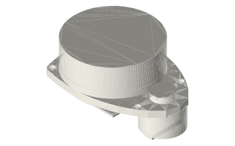
SLAMTEC RPLIDAR A1M8 360° laser scanner: base outline, 4 mounting holes, scanning head and motor
What are the SLAMTEC RPLIDAR A1M8 dimensions and mounting-hole positions? · Modern device · basis: SLAMTEC's official RPLIDAR A1M8 2D drawing, with the base outline, hole depths and under-plate parts taken from SLAMTEC's official 3D model.
Also called: RPLIDAR A1M8, SLAMTEC RPLIDAR A1, rplidar a1, slamtec rplidar a1m8 a1 series 360-degree scanning lidar, RPLIDAR A1 mounting hole pattern, RPLIDAR A1 dimensions, SLAMTEC A1 2D lidar
Exact dimensions. Every file is drawn at true size with no tolerance added. The holes and pins that meet another part are listed below under Mating features, with the fit each joint needs; open those by your process's clearance before making the part. Mating features
- length
- 96.74 mm
- width
- 70.28 mm
- height
- 51.0 mm
Notes
- Upright, lowest point (motor connector) at 0, top of the scanning head at 51.0. Base plate from 21.0 to 26.5 (5.5 thick); the rotating disc is Ø70.28 and the head Ø70.0.
- The head axis sits 35.14 from the head end of the 96.74 base; the Ø32 drive motor hangs below the plate, flush with the opposite end.
- Four Ø3.0 mounting holes through the base plate, each with a Ø5.0 × 2.0 counterbore at the plate top: 70.0 apart along the length, 56.0 apart across at the head end and 40.0 apart across at the motor end.
- Measured from the head axis, the head-end holes sit 28.0 toward the head end and the motor-end holes 42.0 toward the motor end.
- Modelled: base plate outline, holes, skirt and PCB under the plate (down to 15.0), motor and its connector, pulley, rotating disc and head. Not modelled: drive belt, plate ribs, head window and the loose cable.
- All dimensions are exact nominal millimetres, true size, with no tolerance added.
SLAMTEC RPLIDAR A1M8 360° laser scanner: base outline, 4 mounting… size chart
| hole | x from head axis (mm) | y (mm) | diameter (mm) |
|---|---|---|---|
| 1 | -28.0 | +28.0 | 3.0 (Ø5.0 cbore) |
| 2 | -28.0 | -28.0 | 3.0 (Ø5.0 cbore) |
| 3 | +42.0 | +20.0 | 3.0 (Ø5.0 cbore) |
| 4 | +42.0 | -20.0 | 3.0 (Ø5.0 cbore) |
Mating features
Drawn at the exact size. Open press, slide, run and socket features by your process's clearance (tolerances by process); leave designed gaps and clamp fits as drawn.
| feature | exact | mates with | fit | files |
|---|---|---|---|---|
| Base mounting holes | 4 × Ø3.0, 70.0 × 56.0 / 40.0 trapezoid pattern | screws into a mounting plate or standoffs | designed | all |
| Head and disc clearance | Ø70.28 disc from 25.5 to 31.5, Ø70.0 head to 51.0 | sensor tower or cover cut-out around the rotating head | designed | all |
Where the files are
Other publishers' files are linked, not hosted. "verify" = check the license at the link before commercial use.
| SLAMTEC | RPLIDAR A-series support and downloads | web | Publisher's page; dimensions are facts |
| SLAMTEC | RPLIDAR A1M8 R1 2D mechanical drawing (PDF) | web | Publisher's page; dimensions are facts |
| SLAMTEC | RPLIDAR A1M8 R1 3D model (IGES) | web | Publisher's page; dimensions are facts |
Free files
★ Free files 1 parts. Generated by Xem Studio from the standard; threads are plain cylinders at major diameter. CC BY 4.0. index.json
| slamtec-rplidar-a1m8 | SLAMTEC RPLIDAR A1M8 360° laser scanner: base outline, 4 mounting holes, scanning head and motor | STEP · STL |
https://xemstudio.com/mcp to Claude, ChatGPT, Cursor or any MCP client (free, no account, one minute) and it can look up exact sizes, mating fits and free STEP/STL from every chat.Plain text: sheet.txt · JSON: /api/geometry?object=slamtec-rplidar-a1m8
Fits with
Questions
What is the RPLIDAR A1M8 mounting hole pattern?
Four Ø3.0 holes, 70.0 mm apart along the base, 56.0 mm apart across at the head end and 40.0 mm across at the motor end.
How big is the RPLIDAR A1M8?
96.74 × 70.28 × 51.0 mm overall; the scanning head is Ø70.0 and its top is 51.0 mm above the lowest point.
Where is the RPLIDAR A1 head axis?
35.14 mm from the head end of the base; the head-end holes are 28.0 mm and the motor-end holes 42.0 mm from it along the length.