 Xem Studiomeasured geometry
Library › Hardware › Stirling & thermoacoustic ·
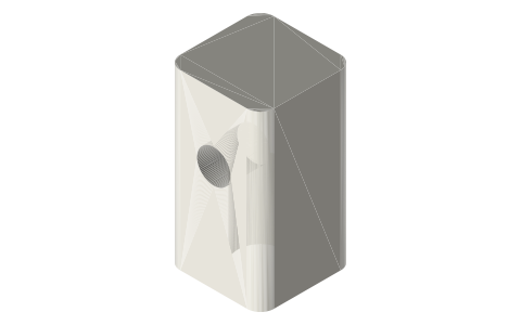
Crosshead yokes with a Ø5 stub wrist pin: Ø6, Ø8 and hollow Ø10 rods
How do I join a con-rod to a piston rod outside the cylinder? · Hardware · basis: Design values; Ø5 dowel (ISO 8734) stub pin with a 625 in the con-rod's small end
Long Earth Society build part. The crossheads of my performance engines. The engines
Exact dimensions. Every file is drawn at true size with no printing tolerance. The holes and pins that meet another part are listed below under Mating features, with the fit each joint needs; open those by your printer's or process's clearance before making the part. Mating features
- sizes
- 3 in table
Notes
- A block on the rod's end with a Ø5 dowel pressed 6 mm into its side: the con-rod's 625 runs on the pin beside the block and a Ø5 shaft collar holds it. The rod's axis stays clear, so in the beta the displacer rod passes straight up through the hollow rod's yoke (and its 6 × 10 × 10 bushing guides it there).
Sizes
| part | socket | pin height | block |
|---|---|---|---|
| yoke-rod6-m6 | M6 × 12 | 15 | 14 × 14 × 24 |
| yoke-rod8-m8 | M8 × 12 | 16 | 14 × 14 × 26 |
| yoke-tube10-m10x1 | M10 × 1 × 16 | 22 | 14 × 24 × 30 |
Mating features
Drawn at the exact size. Open press, slide, run and socket features by your process's clearance; leave designed gaps and clamp fits as drawn.
| feature | exact | mates with | fit | files |
|---|---|---|---|---|
| rod sockets | M6 (Ø5.0 × 12) / M8 (Ø6.8 × 12) / M10 × 1 (Ø9.0 × 16) | rod ends | designed | all |
| stub-pin hole | Ø5 × 6 | Ø5 dowel wrist pin | press | all |
| bushing seat | Ø10 × 10 at the top | 6 × 10 × 10 sleeve bushing (guides the displacer rod) | press | yoke-tube10* |
Where the files are
Other publishers' files are linked, not hosted. "verify" = check the license at the link before commercial use.
| Long Earth Society | Engine builds | web, video | LES site |
Free files
★ Free files 3 parts. Generated by Xem Studio from the standard; threads are plain cylinders at major diameter. CC BY 4.0. index.json
| yoke-rod6-m6 | crosshead yoke 14 × 14 × 24 for the rod6 rod: tapped socket from the bottom, Ø5 stub-pin hole 6 deep in the −Y face at 15 | STEP · STL |
| yoke-rod8-m8 | crosshead yoke 14 × 14 × 26 for the rod8 rod: tapped socket from the bottom, Ø5 stub-pin hole 6 deep in the −Y face at 16 | STEP · STL |
| yoke-tube10-m10x1 | crosshead yoke 14 × 14 × 30 for the tube10 rod: tapped socket from the bottom, Ø5 stub-pin hole 6 deep in the −Y face at 22, Ø7 passage and Ø10 × 10 bushing seat at the top | STEP · STL |
Plain text: sheet.txt · JSON: /api/geometry?object=stirling-crosshead-yokes
How it fits
In these build lists
Tri-clamp horizontal gamma generator, 2 in,…The classic desk Stirling generator in tri-clamp, built for power: a horizontal …Tri-clamp walking-beam gamma generator, 2 in,…The classic desk walking-beam Stirling in tri-clamp: a standard 2 in tee with th…Tri-clamp charged beta, 2 inA standing beta that holds a charge: the same hot spool, liner, regenerator and …Tri-clamp twin walking-beam gamma generator, 2…Two walking-beam tee units side by side on one crank, a quarter turn apart: each…You might also need
Questions
Why not a clevis?
A clevis pin crosses the rod's axis; the beta's coaxial rods need the axis clear.