 Xem Studiomeasured geometry
Tri-clamp twin walking-beam gamma generator, 2 in, chargeable
Two walking-beam tee units side by side on one crank, a quarter turn apart: each with its own closed hot spool over its own burner, its own tee, power cylinder, bounce spool and beam; one crankshaft, one Ø200 flywheel, one belted generator, one base.
Two walking-beam units on one crank, 90° apart · each: displacer Ø40 × 30, piston Ø48 × 36 · model shaft power: air 1 atm 4–9 W at 600 rpm; charged 5 bar gauge: air 12–59 W, helium 28–122 W at 1200 rpm · gas torque at 90°: 0.11–0.47 N·m (one unit -0.32–0.63) · 2208 generator: 1.0–7.1 W at 24–28 V at 1 atm
Exact dimensions. Every part is drawn at true size with no printing tolerance; each part's page lists its mating features and the fit each joint needs, so open those by your process's clearance before making the parts.
Long Earth Society build part. Complete parts list. The engines
58 parts, every one a file here · all STL URLs · Markdown · tick lines as you go (saved in this browser)
| subsystem | object | parts | qty | note | |
|---|---|---|---|---|---|
| None | Frame for the tri-clamp twin walking-bea | twin-walking-beam-gamma-frame-2in STEP · STL | 1 | base, four cradles, two beam posts, crank uprights, generator bracket | |
| None | Torch stand for a horizontal tri-clamp h | torch-stand-40 STEP · STL | 2 | under the shroud's inlet, post toward −Y | |
| None | Set screws (grub screws) | set-m4x10 STEP · STL | 6 | centre the torch head in the stand ring | |
| None | Socket head cap screws | shcs-m4x10 STEP · STL | 8 | torch stand (2), shroud feet (2) | |
| None | Burner shroud for a horizontal finned 2 | burner-shroud-2in-horizontal STEP · STL | 2 | round the fins | |
| None | 2 in × 152.4 mm closed-end hot spool | hot-spool-2in-152.4-closed-bored-48.00 STEP · STL | 2 | on the tee's −X run end | |
| None | Slip-on fin sleeve for a 2 in closed hot | fin-sleeve-2in-9x76 STEP · STL | 2 | optional heat exchanger: slid over the closed end | |
| None | Clamp-on flow water jacket for 2 in tube | water-jacket-half-2in-48-flow STEP · STL | 4 | optional heat exchanger: round the cold end, hose spigots up and down | |
| None | Socket head cap screws | shcs-m4x25 STEP · STL | 8 | optional: water-jacket ears | |
| None | Hex nuts | nut-m4 STEP · STL | 8 | optional: water-jacket ears | |
| None | Annular regenerator screen stack | screen-stack-48x42x40-50mesh STEP · STL | 2 | optional heat exchanger (with the liner): on the liner's neck | |
| None | Slotted heater | liner-2in-slotted-48-40 STEP · STL | 2 | optional heat exchanger (internal insert), pressed into the hot spool: without it the displacer runs in the Ø48.00 bore 4 mm clear, a plain annular-gap engine with far less power | |
| None | Clearance-seal displacer for a Ø40 liner | displacer-shell-38.5x98 STEP · STL | 2 | the shell | |
| None | Clearance-seal displacer for a Ø40 liner | displacer-cap-40-land STEP · STL | 2 | pressed into the shell; land in the liner bore | |
| None | Ground rods | rod-6x315.4-m6 STEP · STL | 2 | displacer rod: through the run plug and the gland cap to its yoke | |
| None | Hex nuts | nut-m6 STEP · STL | 4 | lock nuts: displacer cold face, under the displacer yoke | |
| None | Sanitary clamp tees and short-outlet tee | tee-2in STEP · STL | 2 | equal tee: run along the engine, branch up | |
| None | Filler plugs for a 2 in tee | tee-run-plug-2in-rod6 STEP · STL | 2 | in the run | |
| None | Filler plugs for a 2 in tee | tee-branch-plug-2in STEP · STL | 2 | in the branch, on the run plug | |
| None | 2 in end cap with a bored boss for two 8 | gland-cap-2in-2x-6x10x10-3x-npt14 STEP · STL | 2 | +X run end: displacer-rod gland; fill, gauge, relief | |
| None | Plain sleeve bushings Ø3 to Ø10 ID | bushing-6x10x10 STEP · STL | 4 | in the displacer gland cap | |
| None | 2 in × 3 in spool with the bore finished | spool-2in-3in-bored-48.00 STEP · STL | 2 | power cylinder, on the branch | |
| None | Clearance-seal pistons Ø48.00 × 34 for a | piston-48-gamma-m8 STEP · STL | 2 | Ø48.00, rod up | |
| None | Ground rods | rod-8x304.85-m8 STEP · STL | 2 | piston rod | |
| None | Hex nuts | nut-m8 STEP · STL | 4 | lock nuts: piston boss, under the piston yoke | |
| None | 2 in × 6 in spool with three 1/4 NPT bos | spool-2in-6in-3x-npt14 STEP · STL | 2 | bounce space above the piston | |
| None | 2 in end cap with a bored boss for two 8 | gland-cap-2in-2x-8x12x20 STEP · STL | 2 | closes the bounce spool; the piston rod's gland | |
| None | Plain sleeve bushings Ø3 to Ø10 ID | bushing-8x12x20 STEP · STL | 4 | in the piston-rod gland cap | |
| None | high-pressure-sanitary-clamps | hp-clamp-2in | 10 | hot spool–tee, tee–gland cap, tee–power spool, power–bounce spool, bounce spool–gland cap; rating above the 7 bar gauge relief setting (not drawn here) | |
| None | Tri-clamp gasket | tc-gasket-2in STEP · STL | 10 | the five 2 in joints | |
| None | NPT male thread envelopes 1/8 to 1 in (A | npt-1-4-male STEP · STL | 12 | 1/4 NPT stems: working-space fill, gauge, relief on the gland cap; bounce-space fill, gauge, relief (bodies are the builder's choice) | |
| None | Crosshead yokes with a Ø5 stub wrist pin | yoke-rod6-m6 STEP · STL | 2 | displacer yoke, stub pin toward +Y | |
| None | Crosshead yokes with a Ø5 stub wrist pin | yoke-rod8-m8 STEP · STL | 2 | piston yoke, stub pin toward +Y | |
| None | Dowel pins | dowel-5x20 STEP · STL | 4 | stub wrist pins | |
| None | Set-screw shaft collars Ø3 to Ø12 | collar-5mm STEP · STL | 6 | wrist pins (2), beam end B pin | |
| None | Set-screw shaft collars Ø3 to Ø12 | collar-6mm STEP · STL | 4 | crank pin, beam end A pin | |
| None | Set screws (grub screws) | set-m3x4 STEP · STL | 10 | 5 and 6 mm collars | |
| None | Walking beam for a tri-clamp beam engine | walking-beam-158.07-131.73 STEP · STL | 2 | on the post's pivot | |
| None | Ball bearings | bearing-625 STEP · STL | 10 | beam pivot (2), small ends of the displacer con-rod and both links (3) | |
| None | Dowel pins | dowel-5x30 STEP · STL | 4 | beam pivot pin, beam end B pin | |
| None | Dowel pins | dowel-6x30 STEP · STL | 4 | crank pin, beam end A pin | |
| None | Con-rods and links with a 626 big end an | conrod-626-625-60 STEP · STL | 2 | link A: piston yoke to beam end A | |
| None | Con-rods and links with a 626 big end an | conrod-626-625-488.4 STEP · STL | 2 | link B: crank pin to beam end B | |
| None | Con-rods and links with a 626 big end an | conrod-626-625-100 STEP · STL | 2 | displacer | |
| None | Ball bearings | bearing-626 STEP · STL | 6 | big ends | |
| None | Built-up crank webs for Ø8 shafts and Ø6 | crank-web-56x12-r15 STEP · STL | 2 | one overhung web per unit on the shared shaft, pins a quarter turn apart | |
| None | Ground rods | shaft-8x91 STEP · STL | 1 | the shared crankshaft: both webs, flywheel and pulley | |
| None | Ball bearings | bearing-608 STEP · STL | 2 | crank uprights | |
| None | Flywheels Ø100–Ø200 with hex-nut rim poc | flywheel-200-m12-b8 STEP · STL | 1 | outboard of the uprights | |
| None | Hex nuts M8 | nut-m12 STEP · STL | 18 | one in each rim pocket | |
| None | Set screws (grub screws) | set-m3x6 STEP · STL | 1 | flywheel hub | |
| None | Round-belt generator drive | crank-pulley-84-b8 STEP · STL | 1 | on the crankshaft's free end | |
| None | Set screws (grub screws) | set-m4x6 STEP · STL | 1 | crank-pulley hub | |
| None | 2208 gimbal motor | gimbal-motor-2208-envelope STEP · STL | 1 | the generator: 2208 gimbal outrunner, KV 128, 14.4 Ω (envelope at its published size) | |
| None | Countersunk socket screws | csk-m3x6 STEP · STL | 4 | motor base to the bracket, heads flush | |
| None | Round-belt generator drive | generator-pulley-2208-pd13.33 STEP · STL | 1 | on the motor's rotor top | |
| None | Socket head cap screws | shcs-m2x6 STEP · STL | 4 | generator pulley to the rotor top | |
| None | Round-belt generator drive | round-belt-5-c130 STEP · STL | 1 | drawn on its pitch line) |
Assembled engine
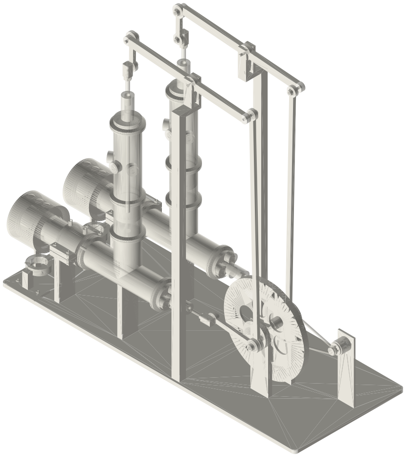
A twin walking-beam gamma Stirling generator in 2 in tri-clamp: two standard-tee units side by side, each with a closed hot spool over its own torch, a bored power spool under a bounce spool and a T-beam on a post, both on one crankshaft a quarter turn apart with one Ø200 flywheel and a belt-driven gimbal-motor generator on one base; about 730 × 277 × 653 mm.
Assembly STEP (9.6 MB) · STL (18.2 MB) · 207 parts
Build order
- Frame; two torch stands, two shrouds, four cradles.
- Build each unit as the walking-beam gamma (unit 2 mirrored: its stub pins and links toward −Y).
- Shaft through both uprights' 608s with the flywheel and the crank pulley between them; press the two webs on with their pins a quarter turn apart; con-rods and links onto the pins.
- Generator, belt.
Agents: each row's object has /api/geometry?object=slug and the MCP tool get_free_files; the STL list above is every part.
JSON: /api/geometry?object=list-tri-clamp-twin-walking-beam-gamma