 Xem Studiomeasured geometry
Tri-clamp charged beta, 2 in
A standing beta that holds a charge: the same hot spool, liner, regenerator and displacer as the horizontal gamma, the bored power spool directly above them, coaxial rods, and a 3 in tee as a sealed crankcase with a shaft seal on the output.
Displacer Ø40 × 30 (37.7 mL) · piston Ø48 × 36 (64.1 mL net of the Ø6 rod) · 90° · dead 66.2 mL (swept/dead 0.97) · charge 5 bar gauge, relief 7 · crankcase buffer 1.52 L · model shaft power: air 17–40 W at 600 rpm, helium 36–82 W at 1200 rpm
Exact dimensions. Every part is drawn at true size with no printing tolerance; each part's page lists its mating features and the fit each joint needs, so open those by your process's clearance before making the parts.
Long Earth Society build part. Complete parts list. The engines
59 parts, every one a file here · all STL URLs · Markdown · tick lines as you go (saved in this browser)
| subsystem | object | parts | qty | note | |
|---|---|---|---|---|---|
| None | Frame for the charged tri-clamp beta | charged-beta-frame-2in STEP · STL | 1 | base, wall, gussets | |
| None | Torch stand for a horizontal tri-clamp h | torch-stand-40 STEP · STL | 1 | under the hot spool, post toward +Y | |
| None | Set screws (grub screws) | set-m4x10 STEP · STL | 3 | centre the torch head in the stand ring | |
| None | Socket head cap screws | shcs-m4x10 STEP · STL | 5 | torch stand (2), shroud feet (3) | |
| None | Burner shroud for a 2 in tri-clamp hot e | burner-shroud-2in STEP · STL | 1 | round the fins | |
| None | 2 in × 152.4 mm closed-end hot spool | hot-spool-2in-152.4-closed-bored-48.00 STEP · STL | 1 | face up, closed end in the shroud | |
| None | Slip-on fin sleeve for a 2 in closed hot | fin-sleeve-2in-9x76 STEP · STL | 1 | optional heat exchanger: slid over the closed end | |
| None | Clamp-on flow water jacket for 2 in tube | water-jacket-half-2in-48-flow STEP · STL | 2 | optional heat exchanger: round the cold end over the cooler zone, hose spigots toward ±Y | |
| None | Socket head cap screws | shcs-m4x25 STEP · STL | 4 | optional: water-jacket ears | |
| None | Hex nuts | nut-m4 STEP · STL | 4 | optional: water-jacket ears | |
| None | Annular regenerator screen stack | screen-stack-48x42x40-50mesh STEP · STL | 1 | optional heat exchanger (with the liner): on the liner's neck | |
| None | Slotted heater | liner-2in-slotted-48-40 STEP · STL | 1 | optional heat exchanger (internal insert), pressed into the hot spool: without it the displacer runs in the Ø48.00 bore 4 mm clear, a plain annular-gap engine with far less power | |
| None | Clearance-seal displacer for a Ø40 liner | displacer-shell-38.5x98 STEP · STL | 1 | the shell | |
| None | Clearance-seal displacer for a Ø40 liner | displacer-cap-40-land STEP · STL | 1 | pressed into the shell; land in the liner bore | |
| None | Ground rods | rod-6x300.25-m6 STEP · STL | 1 | displacer rod: up through the piston's gland and the hollow rod | |
| None | Hex nuts | nut-m6 STEP · STL | 2 | lock nuts: displacer cold face, under the displacer yoke | |
| None | 2 in × 3 in spool with the bore finished | spool-2in-3in-bored-48.00 STEP · STL | 1 | power cylinder, on the hot spool | |
| None | Clearance-seal pistons Ø48.00 × 34 for a | piston-48-beta-gland STEP · STL | 1 | Ø48.00, gland at the crown | |
| None | Plain sleeve bushings Ø3 to Ø10 ID | bushing-6x10x10 STEP · STL | 2 | piston gland, top of the hollow-rod yoke | |
| None | Ground rods | tube-10x7x158.6-m10x1 STEP · STL | 1 | hollow piston rod | |
| None | 2 in double-faced guide plate for a holl | guide-plate-2in-10mm STEP · STL | 1 | between the power spool and the reducer | |
| None | Plain sleeve bushings Ø3 to Ø10 ID | bushing-10x14x15 STEP · STL | 2 | in the guide plate | |
| None | Sanitary clamp reducers | reducer-concentric-3inx2in STEP · STL | 1 | 2 in end down on the guide plate | |
| None | Sanitary clamp tees and short-outlet tee | tee-3in STEP · STL | 1 | the crankcase: branch down, run along the crankshaft | |
| None | 3 in end caps with a bored 608 bearing b | bearing-cap-3in-608-seal STEP · STL | 1 | +X: bearing and shaft seal, the output side | |
| None | 3 in end caps with a bored 608 bearing b | bearing-cap-3in-608-3x-npt14 STEP · STL | 1 | −X: bearing; fill, gauge and relief ports | |
| None | Rotary shaft lip seal 8 × 22 × 7 (envelo | shaft-seal-8x22x7 STEP · STL | 1 | in the +X cap, lip toward the crankcase | |
| None | Ball bearings | bearing-608 STEP · STL | 2 | one in each cap | |
| None | high-pressure-sanitary-clamps | hp-clamp-2in | 3 | hot–power spool, power spool–plate, plate–reducer; rating above the 7 bar gauge relief setting (not drawn here) | |
| None | high-pressure-sanitary-clamps | hp-clamp-3in | 3 | reducer–tee, tee–caps; rating above the 7 bar gauge relief setting (not drawn here) | |
| None | Tri-clamp gasket | tc-gasket-2in STEP · STL | 3 | the three 2 in joints | |
| None | Sanitary clamp gaskets | gasket-3in STEP · STL | 3 | the three 3 in joints | |
| None | NPT male thread envelopes 1/8 to 1 in (A | npt-1-4-male STEP · STL | 3 | 1/4 NPT stems: crankcase fill, gauge, relief (bodies are the builder's choice) | |
| None | Crosshead yokes with a Ø5 stub wrist pin | yoke-tube10-m10x1 STEP · STL | 1 | on the hollow rod, stub pin toward −X | |
| None | Crosshead yokes with a Ø5 stub wrist pin | yoke-rod6-m6 STEP · STL | 1 | on the displacer rod, stub pin toward +X | |
| None | Dowel pins | dowel-5x20 STEP · STL | 2 | stub wrist pins | |
| None | Set-screw shaft collars Ø3 to Ø12 | collar-5mm STEP · STL | 2 | on the wrist pins | |
| None | Set screws (grub screws) | set-m3x4 STEP · STL | 2 | wrist-pin collars | |
| None | Con-rods and links with a 626 big end an | conrod-626-625-120 STEP · STL | 1 | piston | |
| None | Con-rods and links with a 626 big end an | conrod-626-625-55 STEP · STL | 1 | displacer | |
| None | Ball bearings | bearing-626 STEP · STL | 2 | big ends | |
| None | Ball bearings | bearing-625 STEP · STL | 2 | small ends | |
| None | Built-up crank webs for Ø8 shafts and Ø6 | crank-web-56x8-r18 STEP · STL | 1 | −X web, piston pin | |
| None | Built-up crank webs for Ø8 shafts and Ø6 | link-web-14-r18-r15-90 STEP · STL | 1 | between the con-rods: piston pin and displacer pin | |
| None | Built-up crank webs for Ø8 shafts and Ø6 | crank-web-56x8-r15 STEP · STL | 1 | +X web, displacer pin | |
| None | Dowel pins | dowel-6x30 STEP · STL | 2 | crank pins | |
| None | Ground rods | shaft-8x103.95 STEP · STL | 1 | −X crank stub | |
| None | Ground rods | shaft-8x138.3 STEP · STL | 1 | +X crank stub: through the seal to the flywheel | |
| None | Set-screw shaft collars Ø3 to Ø12 | collar-8mm STEP · STL | 2 | inside the bearings: axial location | |
| None | Set screws (grub screws) | set-m4x4 STEP · STL | 2 | 8 mm collars | |
| None | Flywheels Ø100–Ø200 with hex-nut rim poc | flywheel-200-m12-b8 STEP · STL | 1 | outside the +X cap | |
| None | Hex nuts M8 | nut-m12 STEP · STL | 18 | one in each rim pocket | |
| None | Set screws (grub screws) | set-m3x6 STEP · STL | 1 | flywheel hub | |
| None | Spool hanger collars | hanger-2in-tab STEP · STL | 2 | on the power spool, bars to the wall | |
| None | Spool hanger collars | hanger-2in-plain STEP · STL | 2 | close the hangers | |
| None | Socket head cap screws | shcs-m4x20 STEP · STL | 4 | hanger ears | |
| None | Hex nuts | nut-m4 STEP · STL | 4 | hanger ears | |
| None | Socket head cap screws | shcs-m5x25 STEP · STL | 4 | hanger bars through the wall | |
| None | Hex nuts | nut-m5 STEP · STL | 4 | hanger bars |
Assembled engine
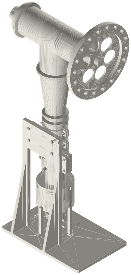
A charged beta Stirling engine in 2 in and 3 in tri-clamp: a closed hot spool standing in a burner shroud over a torch, a bored power spool, a guide plate and reducer up to a 3 in tee crankcase with bearing caps, coaxial rods to a built-up crank and a Ø200 flywheel outside the shaft seal, hung on a wall frame; about 307 × 200 × 667 mm.
Assembly STEP (8.8 MB) · STL (8.8 MB) · 119 parts
Build order
- Frame on the bench; torch stand and shroud on the base.
- Hot end as on the horizontal gamma: screens, liner pressed in, displacer with its rod.
- Gasket, clamp, bored power spool; piston (gland bushing in) over the displacer rod into the bore; hollow rod screwed into the piston.
- Gasket, clamp, guide plate (bushings in) over the hollow rod; gasket, clamp, reducer; hangers on the power spool to the wall.
- Yokes: hollow-rod yoke (bushing in its top) on the tube, displacer yoke with its lock nut on the rod; wrist pins and collars.
- Crank: pins and shafts pressed into the webs and the link web with the con-rods and their bearings between; into the tee through a run end, con-rods onto the wrist pins; tee onto the reducer; collars, bearings, caps with gaskets and clamps, seal; flywheel and its nuts.
Agents: each row's object has /api/geometry?object=slug and the MCP tool get_free_files; the STL list above is every part.