 Xem Studiomeasured geometry
Library › Hardware › Sanitary clamp fittings ·
Tri-clamp end caps with a welded boss (fabrication spec): 2 in cap with a ¾ in ferrule, ¾ in cap with a 1/4 NPT boss
How do I join a small line or an instrument to a 2 inch tri-clamp engine? · Hardware · basis: 16AMP end-cap profile and ISO 2852 faces as gen_sanitary.cap; ¾ in tube Ø19.05 × 1.65 and ferrule; 1/4 NPT tap drill 7/16 in (ASME B1.20.1) with the thread drawn as its drill, the convention of this site's thread envelopes
Used in Long Earth Society builds. Collapsing one-way valve (balloon → duckbill)
Exact dimensions. Every file is drawn at true size with no printing tolerance. The holes and pins that meet another part are listed below under Mating features, with the fit each joint needs; open those by your printer's or process's clearance before making the part. Mating features
- sizes
- 2 in table
Notes
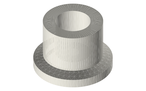
- 2 in cap with a ¾ in ferrule: a standard 2 in cap with a ¾ in tube welded on its axis, ending 25.4 mm out in a full ¾ in ferrule, bored Ø15.75 through. It turns a 2 in end into a ¾ in clamp end without a reducer, clear of the 2 in clamp.
- ¾ in cap with a 1/4 NPT boss: a standard ¾ in cap with a Ø19 boss welded on, tapped 1/4 NPT; a gauge, a fill valve or a relief valve screws in.
- Both are things a sanitary fabricator makes from a drawing: a cap, a short tube or a boss, one weld.
- Fits: faces are clamp faces; the NPT hole is a taper thread (drawn at its tap drill).
Sizes
| file | base | added | bore |
|---|---|---|---|
| cap-2in-x-0.75in-ferrule | 2 in cap | ¾ in ferrule on a 25.4 stub | Ø15.75 |
| cap-0.75in-x-1-4npt | ¾ in cap | Ø19 × 12 boss | 1/4 NPT, Ø4 through |
Mating features
Drawn at the exact size. Open press, slide, run and socket features by your process's clearance; leave designed gaps and clamp fits as drawn.
| feature | exact | mates with | fit | files |
|---|---|---|---|---|
| 2 in cap face | ISO 2852 (16AMP profile) | standard clamp + Type B gasket | clamp | cap-2in-x-* |
| ¾ in ferrule face | ISO 2852, 25.0 flange, 25.4 + 6.35 from the 2 in face | standard ¾ in clamp + Type B gasket | clamp | cap-2in-x-* |
| bore | Ø15.75 through cap and stub | gas passage (no contact) | designed | cap-2in-x-* |
| ¾ in cap face | ISO 2852, 25.0 flange | standard ¾ in clamp + Type B gasket | clamp | cap-0.75in-x-* |
| port | 1/4-18 NPT, tap drill Ø11.1 × 12 (ASME B1.20.1), Ø4 on through | fill valve, pressure gauge or relief valve, 1/4 NPT male | designed | cap-0.75in-x-* |
Where the files are
Other publishers' files are linked, not hosted. "verify" = check the license at the link before commercial use.
| ASME | BPE Bioprocessing Equipment (clamp fitting dimensions, tube OD and wall) | standard | ASME; dimensions are facts verify |
| ISO (via iTeh sample) | ISO 2852 clamp liners: face profile and flange / groove diameters | standard excerpt; dimensions are facts | |
| ASME | ASME B1.20.1 pipe threads (NPT): 1/4 NPT tap drill 7/16 in (11.1 mm) as on this site's thread envelopes | standard | dimensions are facts verify |
| Long Earth Society | Engine builds | web, video | LES site |
Free files
★ Free files 2 parts. Generated by Xem Studio from the standard; threads are plain cylinders at major diameter. CC BY 4.0. index.json
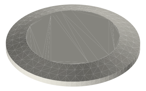
| cap-2in-x-0.75in-ferrule | 2 in end cap (16AMP profile, Ø64 × 6.35) with a ¾ in tube on its axis ending 25.4 mm behind the cap in a full ¾ in ferrule face (Ø25.0); Ø15.75 bore through | STEP · STL |
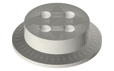
| cap-0.75in-x-1-4npt | ¾ in end cap (25.0 flange, 4.775 thick) with a Ø19 × 12 boss, 1/4 NPT (tap drill Ø11.1) 12 deep, Ø4 on through | STEP · STL |
Plain text: sheet.txt · JSON: /api/geometry?object=tri-clamp-caps-with-welded-boss
How it fits
In these build lists
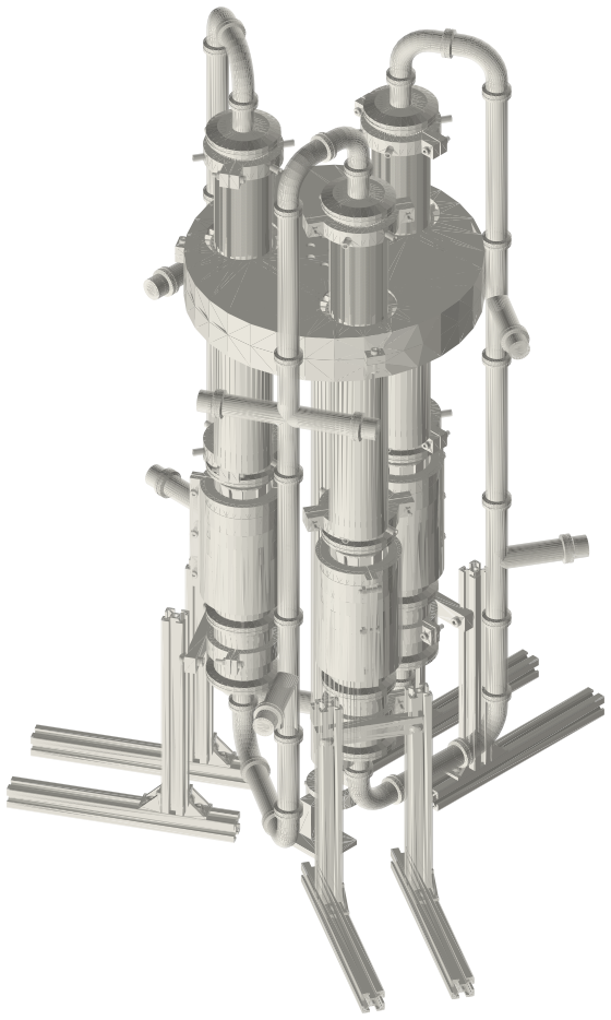
Thermoacoustic-Stirling ring generator, three 2…A double-acting thermoacoustic-Stirling generator in 2 in tri-clamp: three cores…Thermoacoustic-Stirling engine with twin…Backhaus & Swift's thermoacoustic-Stirling torus in 2 in tri-clamp with two oppo…You might also need
Questions
Why not a reducer?
A 2 × ¾ in reducer is long and holds gas; at the core's ambient end every cm³ of dead volume costs power, so the cap with a short stub keeps it small.