 Xem Studiomeasured geometry
Library › Stirling engines › Tri-clamp engine parts ·
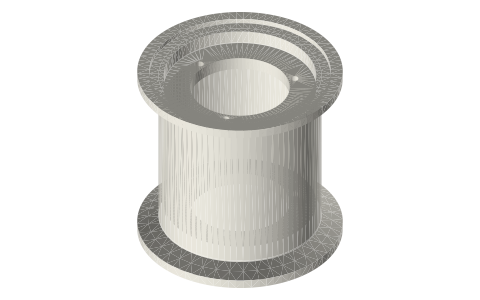
Tri-clamp flexure carrier: clamp-in 2 in, two Ø40 flexure stacks
Where do the flexure bearings of a sealed free piston go in a tri-clamp engine? · Hardware · basis: ISO 2852 faces as the ferrule on this site; ledge hole circle = the Ø40 spiral flexure's rim holes (r 17.6)
Long Earth Society build part. The flexure carriers on my generator pistons. The engines
Exact dimensions. Every file is drawn at true size with no printing tolerance. The holes and pins that meet another part are listed below under Mating features, with the fit each joint needs; open those by your printer's or process's clearance before making the part. Mating features
- sizes
- 3 in table
Notes
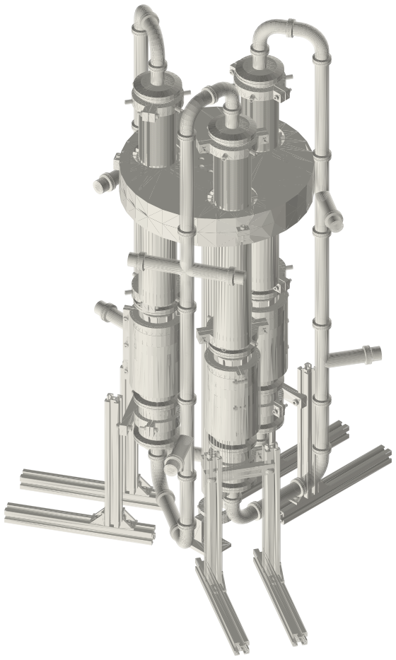
- A part with a full 2 in ferrule face on each side, clamped between the honed cylinder and the next fitting like a thick gasket (each side its own gasket and clamp). Inside, two ledges carry two flexure stacks of Ø40 spiral leaves 48 mm apart, so the piston's rod is held on centre at two points and the mover never touches the bore.
- Stack A hangs under the upper ledge, stack B stands on the lower ledge; each is leaf, spacer, leaf (opposite hand), clamp plate, with three M3 × 10 into the ledge. The rod passes the Ø31 ledge windows; M4 nuts and washers clamp the leaf hubs.
- The carrier's inside is part of the gas space behind the piston.
- Fits: faces are clamp faces; the M3 holes are tap drills; the ledge windows are clearance (designed).
Sizes
| feature | value |
|---|---|
| face to face | 60 |
| ledges | Ø31 window, 4 thick |
| holes | 3 × M3 on r 17.6 |
Mating features
Drawn at the exact size. Open press, slide, run and socket features by your process's clearance; leave designed gaps and clamp fits as drawn.
| feature | exact | mates with | fit | files |
|---|---|---|---|---|
| faces | ISO 2852 both sides (land Ø56.5–Ø64, rim 2.85, 1.6 recess, 20° back to Ø50.8) | standard clamps + Type B gaskets | clamp | all |
| ledge holes | 2 × 3 × Ø2.5 (M3 tap drill) on r 17.6 | shcs-m3x10 through the flexure stacks | designed | all |
| ledge windows | Ø31 × 4 | leaf arms, hubs and hub nuts at ±8 stroke (no contact) | designed | all |
| ledge faces | flat ring Ø31–Ø47.5 | flexure leaf rims | designed | all |
| neck | Ø50.8 | spool hanger (ring engine) | clamp | all |
Where the files are
Other publishers' files are linked, not hosted. "verify" = check the license at the link before commercial use.
| ASME | BPE Bioprocessing Equipment (clamp fitting dimensions, tube OD and wall) | standard | ASME; dimensions are facts verify |
| ISO (via iTeh sample) | ISO 2852 clamp liners: face profile and flange / groove diameters | standard excerpt; dimensions are facts | |
| Long Earth Society | Engine builds | web, video | LES site |
Free files
★ Free files 1 parts. Generated by Xem Studio from the standard; threads are plain cylinders at major diameter. CC BY 4.0. index.json
| flexure-carrier-2in-60 | flexure carrier 60 face to face: ISO 2852 2 in face each side on a Ø50.8 neck, Ø47.5 bore, ledges Ø47.5 / Ø31 × 4 at 6–10 and 50–54 from the top face, 3 × M3 tap drill Ø2.5 on r 17.6 each | STEP · STL |
Plain text: sheet.txt · JSON: /api/geometry?object=tri-clamp-flexure-carrier
How it fits
In these build lists
Thermoacoustic-Stirling ring generator, three 2…A double-acting thermoacoustic-Stirling generator in 2 in tri-clamp: three cores…Thermoacoustic-Stirling engine with twin…Backhaus & Swift's thermoacoustic-Stirling torus in 2 in tri-clamp with two oppo…You might also need
Questions
Why clamp-in?
The stacks must sit inside the pressure boundary on the same axis as the cylinder; a part with a ferrule face both sides does that and keeps every joint a standard clamp joint.