 Xem Studiomeasured geometry
Library › Stirling engines › Free-piston ·
Free-piston Stirling core: displacer, power piston, liner, gas spring, stops, clearance-seal and tuning tables
How do I design a free-piston Stirling engine: displacer, power piston, gas spring and clearance seals? · Hardware · basis: Beta free-piston layout (displacer and power piston in one bore, as Sunpower RE-1000 / NASA convertors): dimensionless rules from the public FPSE literature; parts sized for Ø30 and Ø40 bores to match the flexures, alternator and tube sizes in the library
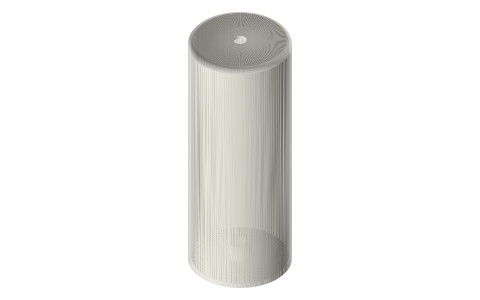
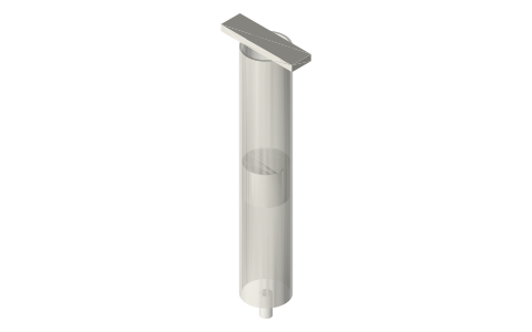
Long Earth Society build part. The LES free-piston test bed: Ø40 core on flexures in a 2 in tri-clamp vessel. The engines · all LES parts
- sizes
- 3 in table
Notes
- No crank: the displacer and power piston are each a mass on a spring (flexure + gas spring) and the engine runs at the resonance f = (1/2π)√(k/m). Thermodynamics sets the phase (displacer leads the piston by ~60–90°) through the displacer's gas spring and rod area, not a linkage. Design order: pick bore D and stroke S (S ≈ 0.3–0.5 D), then piston mass and alternator load, then tune the displacer spring so it leads.
- Clearance seals: the piston runs in the bore with no rings; the radial gap must be small enough that leakage over one cycle is a few % of swept volume. Rule of thumb from the literature: radial gap ≈ 10–20 µm for Ø20–40 mm at 50 Hz; a hobby engine at 10–15 Hz tolerates 25–40 µm. That is a lapped fit (piston turned 0.05 under, lapped into a honed liner), not a printed one: the printed piston blanks here are 0.1 mm under for you to finish, or use a glass syringe (10 mL: Ø14.5) or a graphite piston in a glass liner for a zero-effort seal. Displacer gap is generous (0.5–1 mm radial): it is a shuttle, not a seal.
- Gas spring: a sealed bounce space behind the piston; stiffness k_gas = γ·p·A² / V (γ 1.4 air, p mean pressure, A piston area, V bounce volume). Ø20 gas piston at 1 bar with 20 cm³ bounce → k ≈ 1.4 × 10⁵ × (3.14e-4)² / 2e-5 ≈ 690 N/m. Smaller volume → stiffer. Centring ports (two 0.5 mm holes the piston uncovers at mid-stroke) keep the mean position from drifting.
- Stops: the piston must never hit metal; TPU bumpers at both ends of the stroke, 6 mm tall, stroke limited to 85% of the free travel. Over-stroke is the normal failure when the load drops.
- Dimensionless checks: Beale number ≈ 0.015 for a hobby engine (W = Bn · p_mean · V_swept · f; 1 bar, 10 cm³, 15 Hz → ~0.2 W), 0.1+ for pressurised helium machines; West number ~0.25. Dead volume ratio under 1.5; regenerator porosity 0.7; heater and cooler as copper/stainless tube from the library.
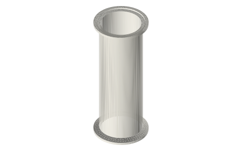
- LES: the Ø40 core on flexures with the linear alternator is the next test bed after the crank engines; the tri-clamp spools are its pressure vessel.
Sizes
| bore_mm | stroke_mm | displacer_len_mm | radial_gap_um_piston | radial_gap_mm_displacer | gas_spring_bore_mm | freq_hz_hobby |
|---|---|---|---|---|---|---|
| 30 | 10–15 | 75 | 25–40 (lapped) | 0.5 | 15 | 10–20 |
| 40 | 12–20 | 100 | 25–40 (lapped) | 0.5 | 20 | 10–20 |
| 60 | 20–30 | 150 | 20–30 | 0.8 | 30 | 10–15 |
Where the files are
Other publishers' files are linked, not hosted. "verify" = check the license at the link before commercial use.
| NASA (NTRS, public domain) | Free-piston Stirling engine design and analysis (RE-1000 test results) (1984) | US Government work, public domain | |
| NASA (NTRS, public domain) | Dynamics of free-piston Stirling engines (1987) | US Government work, public domain | |
| Wikipedia | Free-piston engine | web | CC BY-SA 4.0 (text) |
| Wikipedia | Beale number | web | CC BY-SA 4.0 (text) |
| Ohio University | Stirling cycle machine analysis (Urieli), free online | web | Author's site |
| Long Earth Society | Engine builds | web, video | LES site |
Free files
★ Free files 11 parts. Generated by Xem Studio from the standard; threads are plain cylinders at major diameter. CC BY 4.0. index.json
| displacer-30x75 | displacer Ø29 (0.5 mm radial gap in a Ø30 bore) × 75, hollow 1.2 wall, Ø5 rod boss | STEP · STL |
| power-piston-30x30 | power piston Ø29.9 × 30 (clearance-seal blank: lap to fit), Ø5 rod | STEP · STL |
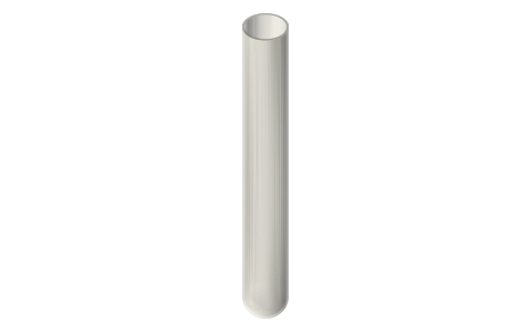
| cylinder-liner-30x120 | cylinder liner Ø30 bore × 120, 3 wall (print to check layout; real liner is honed tube or a glass/brass tube from the library) | STEP · STL |
| gas-spring-piston-15x15 | gas-spring piston Ø14.9 × 15 for a Ø15 bounce-space bore | STEP · STL |
| stop-bumper-30 | end-stop bumper for a Ø30 bore (TPU), 6 tall | STEP · STL |
| displacer-40x100 | displacer Ø39 (0.5 mm radial gap in a Ø40 bore) × 100, hollow 1.2 wall, Ø5 rod boss | STEP · STL |
| power-piston-40x40 | power piston Ø39.9 × 40 (clearance-seal blank: lap to fit), Ø5 rod | STEP · STL |
| cylinder-liner-40x160 | cylinder liner Ø40 bore × 160, 3 wall (print to check layout; real liner is honed tube or a glass/brass tube from the library) | STEP · STL |
| gas-spring-piston-20x20 | gas-spring piston Ø19.9 × 20 for a Ø20 bounce-space bore | STEP · STL |
| stop-bumper-40 | end-stop bumper for a Ø40 bore (TPU), 6 tall | STEP · STL |
| displacer-rod-5x150-grooved | Ø5 × 150 displacer rod with E-clip grooves | STEP · STL |
Plain text: sheet.txt · JSON: /api/geometry?object=free-piston-core
Fits with
Questions
What is the piston clearance in a free-piston Stirling engine?
10–20 µm radial for the real machines at 50+ Hz; 25–40 µm is workable for a slow hobby engine. It is a lapped or honed fit, never a printed one: print the blank, lap it in, or use a glass syringe or graphite-in-glass piston.
How does a free-piston Stirling engine keep its phase without a crank?
The displacer is a tuned mass-spring system (flexure + gas spring on its rod) that resonates slightly ahead of the piston; rod area and gas-spring volume set the phase angle, typically 60–90° lead.
What is the Beale number?
W = Bn · p_mean · V_swept · f with Bn ≈ 0.015 for a low-temperature hobby engine and ~0.1–0.15 for pressurised, high-ΔT machines. 1 bar, 10 cm³, 15 Hz → about 0.2 W.
What stops a free-piston engine from over-stroking?
The load: alternator current is the brake. Plus TPU bumpers at both ends and a stroke limited to 85% of the free travel for when the load drops.