 Xem Studiomeasured geometry
Library › Stirling engines › Free-piston ·
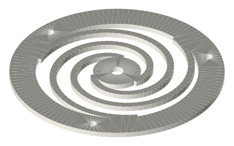
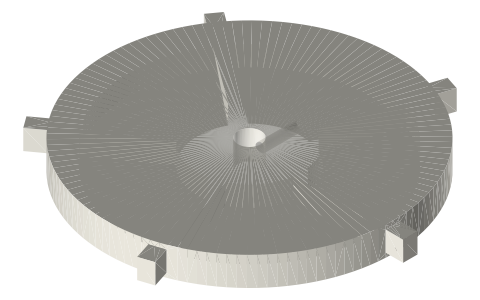
Planar spiral flexure bearings (Sunpower / NASA free-piston style): Ø40–120, DXF + STEP
What is a spiral flexure bearing and how do I make one for a free-piston Stirling engine? · Hardware · basis: Three-arm Archimedean planar springs as used on Sunpower / NASA free-piston Stirling convertors (RE-1000, ASRG, Sunpower EE-35/EG-1000 class) for the displacer and piston suspension; geometry parametrized here, stiffness measured not quoted
Long Earth Society build part. Flexure-suspended displacer on the LES free-piston test bed. The engines · all LES parts
- sizes
- 5 in table
Notes
- A flexure bearing is a stack of flat spiral springs that lets a piston move axially (soft) while holding it on centre (stiff): the free-piston engine's non-contact 'bearing', so the piston runs in a clearance seal with no oil and no wear. NASA's convertors have run for over a decade on them.
- Geometry: 3 arms (radial stiffness symmetric; 2-arm leaves are softer but wobble), each arm sweeping about 330° from the hub to the rim. Axial stiffness per leaf scales with E·t³·w / L³ (L = arm length), so thickness is the big lever: a 0.5 mm steel leaf is ~64× stiffer than a 0.5 mm... halve t and k drops 8×. Stack leaves on spacers to add stiffness in parallel; alternate the spiral hand between leaves to cancel the rotation each spiral induces.
- Materials: spring steel (1095 / C75 / SAE 1074) 0.3–0.8 mm, beryllium copper, or 17-7 PH for the real thing: laser- or water-jet cut from the DXF, deburr, stress-relieve. For demonstrators and motion checks print the 2 mm PETG or nylon versions: they show the motion and survive a few thousand cycles. Stroke limit: keep the leaf's axial deflection under about OD/10 for steel; fatigue life needs stress under ~300 MPa, which means measuring, not guessing: load the stack with known weights, plot deflection, keep the operating stroke in the linear region.
- Natural frequency of the suspended piston: f = (1/2π)·√(k_total/m). Free-piston engines run at this resonance (typically 50–100 Hz for Sunpower-class, 10–20 Hz for hobby builds): tune by adding leaves (k) or mass (m). The gas spring adds to k.
- LES: flexure-suspended displacer on the free-piston test bed; print the stack first, cut steel when the stroke is right.
Sizes
| od_mm | hub_mm | rim_mm | arm_w_mm | thickness | bore_mm | arm_radial_span_mm |
|---|---|---|---|---|---|---|
| 40 | 12 | 4.8 | 1.6 | 0.5 steel / 2.0 print | 4 | 9.2 |
| 60 | 13.2 | 7.2 | 2.0 | 0.5 steel / 2.0 print | 5 | 16.2 |
| 80 | 17.6 | 9.6 | 2.5 | 0.5 steel / 2.0 print | 5 | 21.6 |
| 100 | 22.0 | 12.0 | 3.0 | 0.5 steel / 2.0 print | 8 | 27.0 |
| 120 | 26.4 | 14.4 | 3.5 | 0.5 steel / 2.0 print | 8 | 32.4 |
Where the files are
Other publishers' files are linked, not hosted. "verify" = check the license at the link before commercial use.
| NASA (NTRS, public domain) | Free-piston Stirling convertor flexure bearing development and life testing (2005) | US Government work, public domain | |
| NASA (NTRS, public domain) | Flexure bearing design for free-piston Stirling engines (1986) | US Government work, public domain | |
| NASA (NTRS, public domain) | Advanced Stirling Radioisotope Generator (ASRG) engineering unit (2011) | US Government work, public domain | |
| Wikipedia | Flexure bearing | web | CC BY-SA 4.0 (text) |
| Sunpower (AMETEK) | Free-piston Stirling technology overview | web | Sunpower site verify |
| Long Earth Society | Engine builds | web, video | LES site |
Free files
★ Free files 30 parts. Generated by Xem Studio from the standard; threads are plain cylinders at major diameter. CC BY 4.0. index.json
| flexure-40-3arm-w1.6-t0.5-steel | planar spiral flexure Ø40, 3 arms 1.6 wide, 0.5 thick (laser-cut spring steel / BeCu, DXF included), hub Ø12 bore Ø4, 3 rim holes | STEP · STL · DXF |
| flexure-40-3arm-w1.6-t2-print | planar spiral flexure Ø40, 3 arms 1.6 wide, 2.0 thick (printable PETG/nylon demonstrator), hub Ø12 bore Ø4, 3 rim holes | STEP · STL |
| flexure-40-2arm-w1.6-t0.5-steel | 2-arm variant Ø40 (lower axial stiffness, less radial) | STEP · STL · DXF |
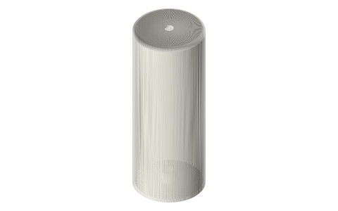
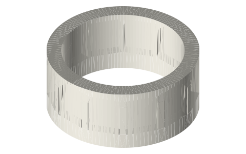
| spacer-40-t2 | stack spacer ring Ø40, 4.8 wide, 2 thick (sets the gap between leaves) | STEP · STL |
| clamp-plate-40 | rim clamp plate Ø40, 3 × M3 | STEP · STL |
| hub-clamp-40-b4 | hub clamp washer Ø12, Ø4 bore | STEP · STL |
| flexure-60-3arm-w2-t0.5-steel | planar spiral flexure Ø60, 3 arms 2.0 wide, 0.5 thick (laser-cut spring steel / BeCu, DXF included), hub Ø13.2 bore Ø5, 3 rim holes | STEP · STL · DXF |
| flexure-60-3arm-w2-t2-print | planar spiral flexure Ø60, 3 arms 2.0 wide, 2.0 thick (printable PETG/nylon demonstrator), hub Ø13.2 bore Ø5, 3 rim holes | STEP · STL |
| flexure-60-2arm-w2-t0.5-steel | 2-arm variant Ø60 (lower axial stiffness, less radial) | STEP · STL · DXF |
| spacer-60-t2 | stack spacer ring Ø60, 7.2 wide, 2 thick (sets the gap between leaves) | STEP · STL |
| clamp-plate-60 | rim clamp plate Ø60, 3 × M3 | STEP · STL |
| hub-clamp-60-b5 | hub clamp washer Ø13.2, Ø5 bore | STEP · STL |
| flexure-80-3arm-w2.5-t0.5-steel | planar spiral flexure Ø80, 3 arms 2.5 wide, 0.5 thick (laser-cut spring steel / BeCu, DXF included), hub Ø17.6 bore Ø5, 3 rim holes | STEP · STL · DXF |
| flexure-80-3arm-w2.5-t2-print | planar spiral flexure Ø80, 3 arms 2.5 wide, 2.0 thick (printable PETG/nylon demonstrator), hub Ø17.6 bore Ø5, 3 rim holes | STEP · STL |
| flexure-80-2arm-w2.5-t0.5-steel | 2-arm variant Ø80 (lower axial stiffness, less radial) | STEP · STL · DXF |
| spacer-80-t2 | stack spacer ring Ø80, 9.6 wide, 2 thick (sets the gap between leaves) | STEP · STL |
| clamp-plate-80 | rim clamp plate Ø80, 3 × M3 | STEP · STL |
| hub-clamp-80-b5 | hub clamp washer Ø17.6, Ø5 bore | STEP · STL |
| flexure-100-3arm-w3-t0.5-steel | planar spiral flexure Ø100, 3 arms 3.0 wide, 0.5 thick (laser-cut spring steel / BeCu, DXF included), hub Ø22 bore Ø8, 3 rim holes | STEP · STL · DXF |
| flexure-100-3arm-w3-t2-print | planar spiral flexure Ø100, 3 arms 3.0 wide, 2.0 thick (printable PETG/nylon demonstrator), hub Ø22 bore Ø8, 3 rim holes | STEP · STL |
| flexure-100-2arm-w3-t0.5-steel | 2-arm variant Ø100 (lower axial stiffness, less radial) | STEP · STL · DXF |
| spacer-100-t2 | stack spacer ring Ø100, 12 wide, 2 thick (sets the gap between leaves) | STEP · STL |
| clamp-plate-100 | rim clamp plate Ø100, 3 × M3 | STEP · STL |
| hub-clamp-100-b8 | hub clamp washer Ø22, Ø8 bore | STEP · STL |
| flexure-120-3arm-w3.5-t0.5-steel | planar spiral flexure Ø120, 3 arms 3.5 wide, 0.5 thick (laser-cut spring steel / BeCu, DXF included), hub Ø26.4 bore Ø8, 3 rim holes | STEP · STL · DXF |
| flexure-120-3arm-w3.5-t2-print | planar spiral flexure Ø120, 3 arms 3.5 wide, 2.0 thick (printable PETG/nylon demonstrator), hub Ø26.4 bore Ø8, 3 rim holes | STEP · STL |
| flexure-120-2arm-w3.5-t0.5-steel | 2-arm variant Ø120 (lower axial stiffness, less radial) | STEP · STL · DXF |
| spacer-120-t2 | stack spacer ring Ø120, 14.4 wide, 2 thick (sets the gap between leaves) | STEP · STL |
| clamp-plate-120 | rim clamp plate Ø120, 3 × M3 | STEP · STL |
| hub-clamp-120-b8 | hub clamp washer Ø26.4, Ø8 bore | STEP · STL |
Plain text: sheet.txt · JSON: /api/geometry?object=spiral-flexure-bearings
Fits with
Questions
What is a flexure bearing in a Stirling engine?
A stack of flat spiral springs that holds the piston centred while letting it move axially, so it can run in a clearance seal with no contact, no oil and no wear; the suspension used in NASA's free-piston convertors.
How many arms should a spiral flexure have?
Three: radial stiffness is then the same in every direction. Two-arm leaves are softer axially but let the hub tilt; stack leaves with alternating spiral hand to cancel rotation.
What material for flexure springs?
Spring steel (1074/1095, C75) 0.3–0.8 mm, beryllium copper, or 17-7 PH stainless, laser or water-jet cut from the DXF; printed PETG/nylon 2 mm leaves for motion checks only.
How do I set the frequency of a free-piston engine?
f = (1/2π)√(k/m): measure the stack stiffness with weights, weigh the moving assembly, and add leaves or mass until the resonance sits where the thermodynamics want it (10–20 Hz for a hobby engine).