 Xem Studiomeasured geometry
Library › Stirling engines › Drives & mechanisms ·
Gamma frame: base plates for tri-clamp engines, rocker beam and pivot post
What frame do I need to mount a tri-clamp Stirling engine with its crank? · Hardware · basis: Base plate sized to the ISO 2852 flange of each spool size with slotted crank-stand mounts and the 2020 hole pattern; classic beam-driven gamma uses a rocker beam on a 623 pivot to drive the displacer from the crank
Long Earth Society build part. Frame for the LES 2 in gamma on 2020. The engines
- sizes
- 5 in table
Notes
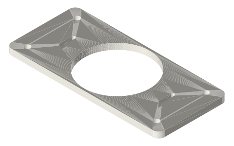
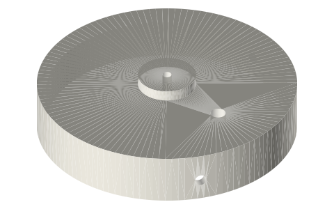
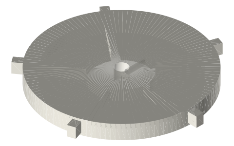
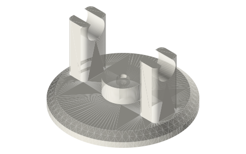
- Base plate: the spool (or its cap) sits in the bore; crank stands bolt into the slots so the crank height and rod alignment can be set; four M5 holes drop it onto 2020 extrusion or any bench. Print in PETG 6 mm, or use it as a drilling template for aluminium.
- Rocker beam: pivot in the middle on a 623 bearing on the post; one end to the crank con-rod, the other to the displacer rod. It converts the crank's motion to the displacer stroke with a lever ratio (set by where the pins sit) and lets the crank sit beside the engine instead of above it: the classic 'beam engine' gamma. Ratio 1:1 at the end holes; drill nearer the pivot for a shorter displacer stroke.
- Everything mounts on Ø3 pins and M3 screws; stands and heads from the other entries.
Sizes
| part | size | fits |
|---|---|---|
| base plate 1.5 in | 140 × 70 × 6 | 50.5 flange |
| base plate 2 in | 154 × 70 × 6 | 64 flange |
| base plate 3 in | 181 × 70 × 6 | 91 flange |
| rocker beam | 60 / 80 / 100 | 623 pivot, Ø3 ends |
| pivot post | 60 tall | M3 foot |
Where the files are
Other publishers' files are linked, not hosted. "verify" = check the license at the link before commercial use.
| Wikipedia | Beam engine | web | CC BY-SA 4.0 (text) |
| Wikipedia | Stirling engine | web | CC BY-SA 4.0 (text) |
| Long Earth Society | Engine builds | web, video | LES site |
Free files
★ Free files 7 parts. Generated by Xem Studio from the standard; threads are plain cylinders at major diameter. CC BY 4.0. index.json
| base-plate-1.5in | base plate for a 1.5 in tri-clamp engine: spool bore, slotted crank-stand mounts, 4 × M5 to 2020 extrusion, 6 thick | STEP · STL |
| base-plate-2in | base plate for a 2 in tri-clamp engine: spool bore, slotted crank-stand mounts, 4 × M5 to 2020 extrusion, 6 thick | STEP · STL |
| base-plate-3in | base plate for a 3 in tri-clamp engine: spool bore, slotted crank-stand mounts, 4 × M5 to 2020 extrusion, 6 thick | STEP · STL |
| rocker-beam-60 | rocker beam 60 mm, centre pivot on a 623, Ø3.2 ends (beam-driven displacer) | STEP · STL |
| rocker-beam-80 | rocker beam 80 mm, centre pivot on a 623, Ø3.2 ends (beam-driven displacer) | STEP · STL |
| rocker-beam-100 | rocker beam 100 mm, centre pivot on a 623, Ø3.2 ends (beam-driven displacer) | STEP · STL |
| pivot-post-60 | beam pivot post 60 mm, Ø3 pin, 2 × M3 foot | STEP · STL |
Plain text: sheet.txt · JSON: /api/geometry?object=gamma-base-plate-and-beam
How it fits
Parts that fit it
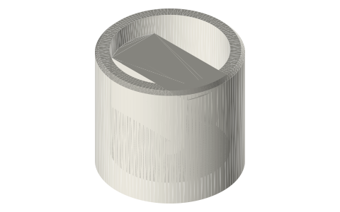 Power cylinder liners, piston blanks, crosshead…liner on the base plate
Goes in or on
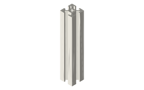 Aluminium T-slot extrusion4 × M5 to 2020
Connects to
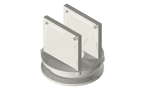 Stirling linkage fittings625 crank stands in the slots
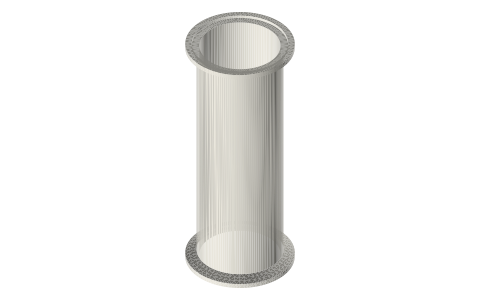 Tri-clamp spool, 1.5 and 2 inchspool bore
Also needed
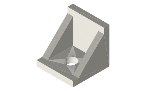 T-slot attachmentsT-nuts
In these build lists
Gamma Stirling, 2 in tri-clampThe Long Earth Society engine: hot spool, shell displacer, graphite or syringe p…You might also need
Questions
How do I mount a tri-clamp Stirling engine?
Base plate with the spool bore and slotted crank-stand mounts; bolt it to 2020 extrusion with M5 button heads or to a board.
What is a beam-driven Stirling engine?
The crank drives a rocker beam whose far end lifts the displacer: the crank can sit beside the cylinder and the beam's lever ratio sets the displacer stroke.