 Xem Studiomeasured geometry
Library › Stirling engines › Drives & mechanisms ·
Stirling linkage fittings: rod clevises, shaft adapter, 625 crank stands, Ø3 crank discs, rhombic frame heads
What small fittings connect a Stirling engine's rods, cranks, flywheel and rhombic drive together? · Hardware · basis: The Ø3 rod / Ø5 shaft / 623-625-608 bearing / M3 conventions used across the shelf; rhombic kit plates 80 × 50 with 625 pockets on 32 mm centres and M3 holes at (±20, −15)
Long Earth Society build part. The connectors between rods, cranks and drives on the LES engines. The engines
- sizes
- 8 in table
Notes
- These are the parts that were missing between the kits: a plain Ø3 displacer rod had no way to take a con-rod (rod clevis: grub on the rod, 623 end on its pin); the Ø100 flywheel has a Ø8 bore and the gamma crankshaft is Ø5 (shaft adapter); the can-engine stands carry 623s but the gamma shaft needs 625s (crank stands); the crank head's towers take a Ø3 crankshaft and no disc had a Ø3 bore (crank discs b3); the rhombic gear plates had nothing to stand on (rhombic frame head).
- Gamma, 2 in, crank on the base plate: displacer rod Ø3 → rod-clevis-3mm → conrod-50 → cw-crank-disc on a Ø5 shaft in two crank-stand-625-h60 → shaft-adapter-5-to-8 → flywheel-100. Piston side: crosshead-8mm-rod3 (its own clevis) → conrod-40 → second crank disc 90° behind.
- Gamma, crank on the head: head-crank-2in (623 towers, Ø3 shaft) + crank-disc-b3 + conrod-40 to a rod clevis; flywheel-50 (Ø5 bore) needs a Ø3 → Ø5 bushing: use bushing-3x5x6 from the bearing housings entry.
- Beta, rhombic, 2 in: -rod piston + piston plug + 5 mm tube rod → yoke-lower-piston; displacer Ø3 rod through the tube → yoke-upper-displacer; gear frame plates on the rhombic frame head, 625s in the plates, Ø5 shafts, gears meshed 180° apart. Gear axes 70 mm above the ferrule face so the lower yoke clears the plug stub at bottom dead centre (yoke travel 32–48 mm below the gear line).
- Rhombic plates now specify 625 bearings (the earlier note said 623; the gears have Ø5 bores).
- LES: the bits between the kits.
Sizes
| spool | part | use |
|---|---|---|
| 1.5 | rhombic head | gear axes 70 mm above face; plates on M3 × 10 |
| 2 | rhombic head | gear axes 70 mm above face; plates on M3 × 10 |
| 3 | rhombic head | gear axes 70 mm above face; plates on M3 × 10 |
| any | rod-clevis-3mm | displacer rod → con-rod (623 end on the Ø3 pin) |
| any | rod-clevis-5mm-tube | tube piston rod → con-rod |
| any | shaft-adapter-5-to-8 | Ø8 flywheel on Ø5 crank |
| any | crank-stand-625 | 40 / 60 mm axis height, 625 bearing |
| any | crank-disc-b3 | for a Ø3 crankshaft: the crank head's 623 towers or the can engine's skewer |
Where the files are
Other publishers' files are linked, not hosted. "verify" = check the license at the link before commercial use.
| Long Earth Society | Tri-clamp Stirling engine builds | web, video | LES site |
Free files
★ Free files 11 parts. Generated by Xem Studio from the standard; threads are plain cylinders at major diameter. CC BY 4.0. index.json
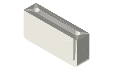
| rod-clevis-3mm | clevis for a Ø3 displacer or piston rod: Ø3.1 socket 12 deep with M3 grub, 5.2 mm gap, Ø3 pin: takes a con-rod's 623 end | STEP · STL |
| rod-clevis-5mm-tube | clevis for the 5 mm tube piston rod: Ø5.1 socket with M3 grub, 5.2 mm gap, Ø3 pin | STEP · STL |
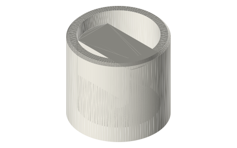
| shaft-adapter-5-to-8 | Ø5 → Ø8 shaft adapter × 20 with two M3 grubs: puts a Ø8-bore flywheel (Ø80–150) on a Ø5 crankshaft | STEP · STL |
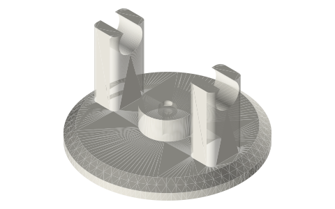
| crank-stand-625-h40 | crank stand, Ø5 shaft axis 40 mm up, Ø16.2 pocket for a 625 bearing, slotted feet 2 × M3 at 42 mm (print two; fits the gamma base plate slots) | STEP · STL |
| crank-stand-625-h60 | crank stand, Ø5 shaft axis 60 mm up, Ø16.2 pocket for a 625 bearing, slotted feet 2 × M3 at 42 mm (print two; fits the gamma base plate slots) | STEP · STL |
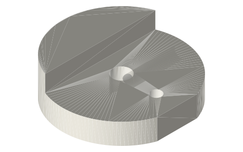
| crank-disc-b3-stroke10 | crank disc Ø30 for a Ø3 crankshaft (the crank head's 623 towers), pin at 5.0 mm (10 mm stroke), M3 grub | STEP · STL |
| crank-disc-b3-stroke15 | crank disc Ø30 for a Ø3 crankshaft (the crank head's 623 towers), pin at 7.5 mm (15 mm stroke), M3 grub | STEP · STL |
| crank-disc-b3-stroke20 | crank disc Ø30 for a Ø3 crankshaft (the crank head's 623 towers), pin at 10.0 mm (20 mm stroke), M3 grub | STEP · STL |
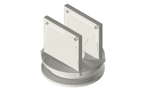
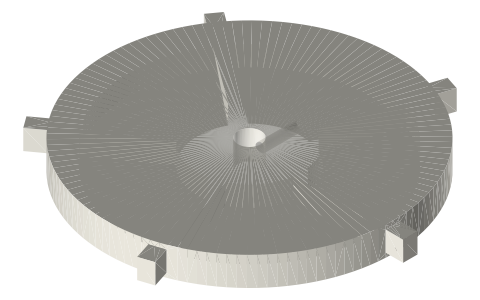
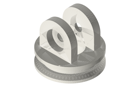
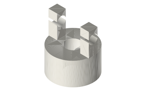
| rhombic-frame-head-1.5in | 1.5 in rhombic frame head: ISO 2852 cap face, pedestal, two uprights 24 mm apart with 2 × M3 at ±20 mm, 55 mm above the face, matching the rhombic gear frame plates' mounting holes; gear axes land 70 mm above the face | STEP · STL |
| rhombic-frame-head-2in | 2 in rhombic frame head: ISO 2852 cap face, pedestal, two uprights 24 mm apart with 2 × M3 at ±20 mm, 55 mm above the face, matching the rhombic gear frame plates' mounting holes; gear axes land 70 mm above the face | STEP · STL |
| rhombic-frame-head-3in | 3 in rhombic frame head: ISO 2852 cap face, pedestal, two uprights 24 mm apart with 2 × M3 at ±20 mm, 55 mm above the face, matching the rhombic gear frame plates' mounting holes; gear axes land 70 mm above the face | STEP · STL |
Plain text: sheet.txt · JSON: /api/geometry?object=stirling-linkage-fittings
How it fits
Goes in or on
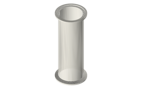 Tri-clamp spool, 1.5 and 2 inchrhombic frame head clamps on its ferrule
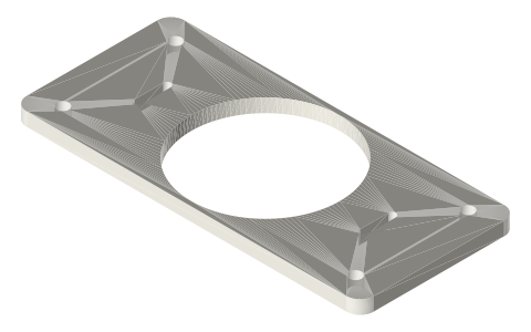 Gamma framecrank stands bolt into the base plate slots
Connects to
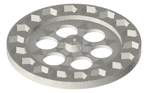 Nut-weighted flywheelsØ5-hub flywheel on the crank stands' shaft
 Crank discs, connecting rods and flywheels for…con-rods onto the clevises; flywheel on the 5→8 adapter
 Counterweighted crank discs, crank webs and…crank discs on the shaft in the 625 stands
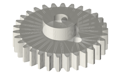 Rhombic drive kitgear plates onto the rhombic frame head
Also needed
 Stirling shafts and rodsØ5 D-flat crankshaft, Ø3 pins, spacers
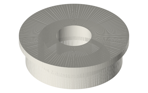 Ball bearings, 683 to 6210 and flanged F6xx625 in the stands, 623 in the con-rods
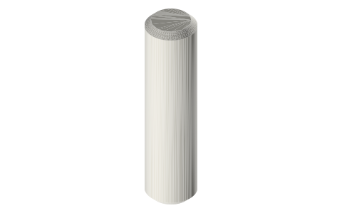 Dowel pins, 2–6 mmØ3 clevis and crank pins
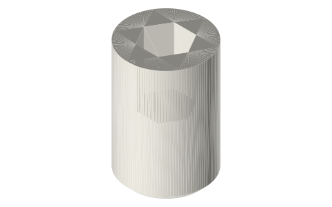 Set screws, M3–M8M3 grubs
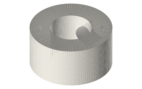 Shafts, D-flats, set-screw collars, E-clips and…Ø5 crankshaft
In these build lists
Gamma Stirling, 2 in tri-clampThe Long Earth Society engine: hot spool, shell displacer, graphite or syringe p…Soda-can gammaCan, tea light, foam, syringe, skewer, CD: the first engine, no budget.Beta Stirling, rhombic drive, 2 in tri-clampDisplacer and piston in one bore, two counter-rotating gears: the balanced one.LTD coffee-cup engineRuns on a cup of coffee: wide thin displacer, tiny piston.You might also need
Questions
How do I connect a plain 3 mm displacer rod to a connecting rod?
Rod clevis: its Ø3.1 socket slides on the rod and an M3 grub locks it; the con-rod's 623 end sits in the 5.2 mm gap on a Ø3 pin.
The flywheel has an 8 mm bore and my crankshaft is 5 mm. What now?
The Ø5 → Ø8 shaft adapter: a 20 mm sleeve with two grubs, one on the shaft and one under the flywheel's set screw.
How does the rhombic drive attach to a tri-clamp spool?
The rhombic frame head clamps on the spool's open ferrule like any cap; its two uprights take the gear frame plates on M3 screws, putting the gear axes 70 mm above the face.