 Xem Studiomeasured geometry
Library › Hardware › Stirling & thermoacoustic ·
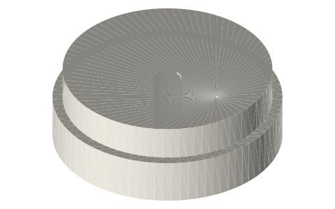
Clearance-seal displacer for a Ø40 liner: Ø40.00 running land, Ø38.50 body, 106 long
How should a displacer seal in a Stirling engine with an external regenerator? · Hardware · basis: Design values; shuttle loss after Martini; land and gap sizes set by the cycle model
Used in Long Earth Society builds. Stirling engine displacer build (8" × 6"), aluminum flashing · Stirling engine displacer build (full walkthrough)
Exact dimensions. Every file is drawn at true size with no printing tolerance. The holes and pins that meet another part are listed below under Mating features, with the fit each joint needs; open those by your printer's or process's clearance before making the part. Mating features
- sizes
- 3 in table
Notes
- The gas must go through the slotted heater, screens and cooler, not round the displacer. A short running land Ø40.00 × 8 at the cold end is a clearance seal in the liner bore; the body behind it is Ø38.50, a designed 0.75 mm radial gap that keeps the shuttle conduction low (the land is cold, the gap is where the temperature changes).
- Stroke 30 mm in both engines; the cold face comes to 10 mm from the hot spool's face and the hot end to 3.4 mm from the floor.
- The cap's Ø0.5 vent lets the inside follow the mean charge slowly, so the shell never carries the charge pressure; the rod screws into the cap's M6 hole and is locked by an M6 nut on the cold face.
Sizes
| part | od_mm | length_mm | fit |
|---|---|---|---|
| cap land | 40.0 | 8.0 | run (liner bore) |
| cap spigot | 36.5 | 6.0 | press (shell bore) |
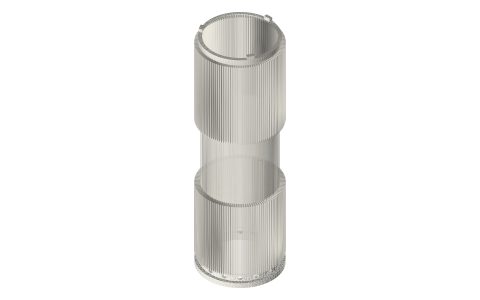
| shell | 38.5 | 98.0 | designed 0.75 gap |
Mating features
Drawn at the exact size. Open press, slide, run and socket features by your process's clearance; leave designed gaps and clamp fits as drawn.
| feature | exact | mates with | fit | files |
|---|---|---|---|---|
| land | Ø40.00 × 8 | liner bore Ø40.00 (clearance seal) | run | displacer-cap* |
| spigot | Ø36.50 × 6 | shell bore Ø36.50 | press | displacer-cap* |
| rod hole | M6 tapped (Ø5.0) × 12 | Ø6 rod, M6 end | designed | displacer-cap* |
| vent | Ø0.5 | lets the inside follow the mean charge | designed | displacer-cap* |
| body | Ø38.50 | liner bore Ø40.00: 0.75 radial gap | designed | displacer-shell* |
| shell bore | Ø36.50 | cap spigot | press | displacer-shell* |
Where the files are
Other publishers' files are linked, not hosted. "verify" = check the license at the link before commercial use.
| NASA (W. R. Martini) | Stirling Engine Design Manual, 2nd edition, NASA CR-168088 (1983): decoupled second-order losses (shuttle, conduction, flow friction, regenerator) | US government report | |
| Long Earth Society | Engine builds | web, video | LES site |
Free files
★ Free files 2 parts. Generated by Xem Studio from the standard; threads are plain cylinders at major diameter. CC BY 4.0. index.json
| displacer-shell-38.5x98 | displacer shell Ø38.50 × 98 (z 8–106), wall 1, closed hot end 1.5 with a 1.0 round | STEP · STL |
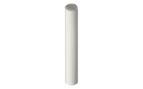
| displacer-cap-40-land | displacer cold cap: running land Ø40.00 × 8, spigot Ø36.50 × 6 into the shell (press), M6 tapped (Ø5.0) × 12, Ø0.5 vent | STEP · STL |
Plain text: sheet.txt · JSON: /api/geometry?object=stirling-clearance-seal-displacer
How it fits
In these build lists
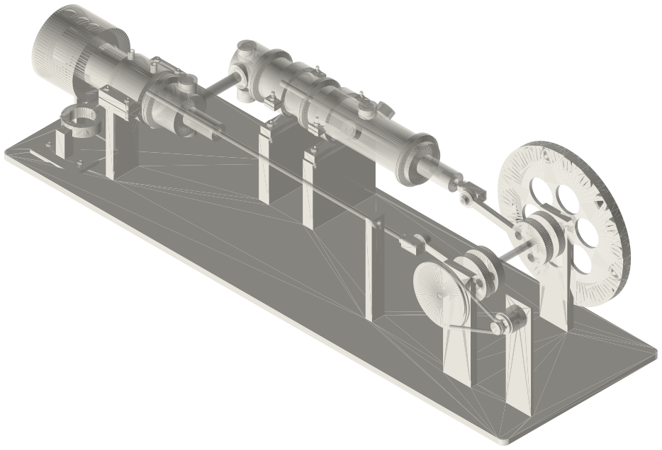
Tri-clamp horizontal gamma generator, 2 in,…The classic desk Stirling generator in tri-clamp, built for power: a horizontal …Tri-clamp walking-beam gamma generator, 2 in,…The classic desk walking-beam Stirling in tri-clamp: a standard 2 in tee with th…Tri-clamp charged beta, 2 inA standing beta that holds a charge: the same hot spool, liner, regenerator and …Tri-clamp twin walking-beam gamma generator, 2…Two walking-beam tee units side by side on one crank, a quarter turn apart: each…You might also need
Questions
Why a land only at the cold end?
A close fit along the whole length would carry heat from hot to cold on every stroke (shuttle loss scales with 1 / gap); the land seals where it is cold.