 Xem Studiomeasured geometry
Library › Hardware › Stirling & thermoacoustic ·
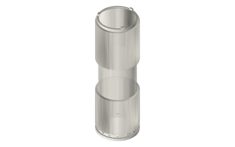
Slotted heater, regenerator and cooler liner for a 2 in hot spool (Ø48.00 / Ø40.00)
How do I put a real heater, regenerator and cooler inside a single tri-clamp hot tube? · Hardware · basis: Design values; slot heat transfer and friction from the laminar rectangular-duct values (Shah & London) and the cycle model on the engine pages
Long Earth Society build part. Heater, regenerator and cooler in one part, inside one tube. The engines
Exact dimensions. Every file is drawn at true size with no printing tolerance. The holes and pins that meet another part are listed below under Mating features, with the fit each joint needs; open those by your printer's or process's clearance before making the part. Mating features
- sizes
- 8 in table
Notes
- The displacer runs in the liner's Ø40.00 bore. The gas does not go round the displacer: it goes out through the liner, along 120 slots 0.5 wide and 3 deep cut in its outside under the flame (the heater), through the annular screen stack on its Ø42 neck (the regenerator), along the same slots under the water jacket (the cooler) and in through 16 ports at the cold end.
- The slots' fin tips are Ø48.00, a press fit in the finished bore, so the heat crosses from the spool wall into the fins. Heater 50 mm, regenerator 40 mm, cooler 45 mm.
- Slot gas volume: heater 9.0 mL, cooler 8.1 mL. Wetted area: about 42 cm² in each of heater and cooler, against about 75 cm² of plain bore.
- Fitting: the screen stack goes on the neck first, then the liner is pressed (or shrunk) into the hot spool until its feet touch the floor; the cold end then sits 1.95 mm inside the face, where the Type B gasket's lip holds it.
Sizes
| zone | z from the spool face | size |
|---|---|---|
| cold ring | 1.95–5 | Ø48.00 (slide) |
| plenum + ports | 5–9 | Ø44, 16 × Ø3 at z 7 |
| cooler slots | 9–54 | 120 × 0.5 × 3, tips Ø48.00 |
| regenerator neck | 54–94 | Ø42.00 |
| heater slots | 94–144 | 120 × 0.5 × 3, tips Ø48.00 |
| hot plenum | 144–147.4 | Ø44 |
| feet | 147.4–149.4 | 3 × 4 wide |
| bore | Ø40.00 (displacer land: run) |
Mating features
Drawn at the exact size. Open press, slide, run and socket features by your process's clearance; leave designed gaps and clamp fits as drawn.
| feature | exact | mates with | fit | files |
|---|---|---|---|---|
| cold ring OD | Ø48.00, z 1.95–5 | hot-spool finished bore | slide | all |
| fin tips | Ø48.00, 120 slots 0.5 wide, z 9–54 and 94–144 | hot-spool finished bore (the heat path) | press | all |
| regenerator neck | Ø42.00 × 40 | screen stack bore | slide | all |
| bore | Ø40.00 × 145.45 | displacer land Ø40.00 | run | all |
| cold end face | annulus Ø40–Ø48 at z 1.95 | Type B gasket lip (holds the liner) | designed | all |
| feet | 3 × 4 wide, to z 149.4 | hot-spool floor | designed | all |
Where the files are
Other publishers' files are linked, not hosted. "verify" = check the license at the link before commercial use.
| Academic Press (R. K. Shah, A. L. London) | Laminar Flow Forced Convection in Ducts (1978): fRe of rectangular ducts | book | book; correlation cited verify |
| Ohio University (I. Urieli) | Stirling cycle machine analysis (after Urieli & Berchowitz, Stirling Cycle Engine Analysis, 1984): Schmidt and simple analyses, wire-screen regenerator friction fr = 54 + 1.43 Re^0.78 and St = 0.46 Re^−0.4 / Pr | web | university course pages verify |
| NASA (W. R. Martini) | Stirling Engine Design Manual, 2nd edition, NASA CR-168088 (1983): decoupled second-order losses (shuttle, conduction, flow friction, regenerator) | US government report | |
| Cambridge University Press (J. R. Senft) | Mechanical Efficiency of Heat Engines (2007): shaft work = E·W − (1/E − E)·W_forced | book | book; formula cited verify |
| Long Earth Society | Engine builds | web, video | LES site |
Free files
★ Free files 1 parts. Generated by Xem Studio from the standard; threads are plain cylinders at major diameter. CC BY 4.0. index.json
| liner-2in-slotted-48-40 | slotted heater / regenerator / cooler liner for the Ø48.00 hot spool: bore Ø40.00 × 145.45; cold ring Ø48.00; plenum Ø44 with 16 × Ø3 ports; cooler and heater: 120 slots 0.5 wide from the Ø48.00 tips to the Ø42.00 root (45 and 50 long); regenerator neck Ø42.00 × 40; three 4 mm feet | STEP · STL |
Plain text: sheet.txt · JSON: /api/geometry?object=stirling-slotted-regenerator-liner
How it fits
In these build lists
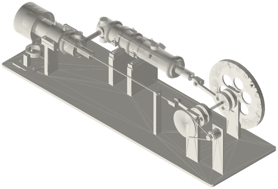
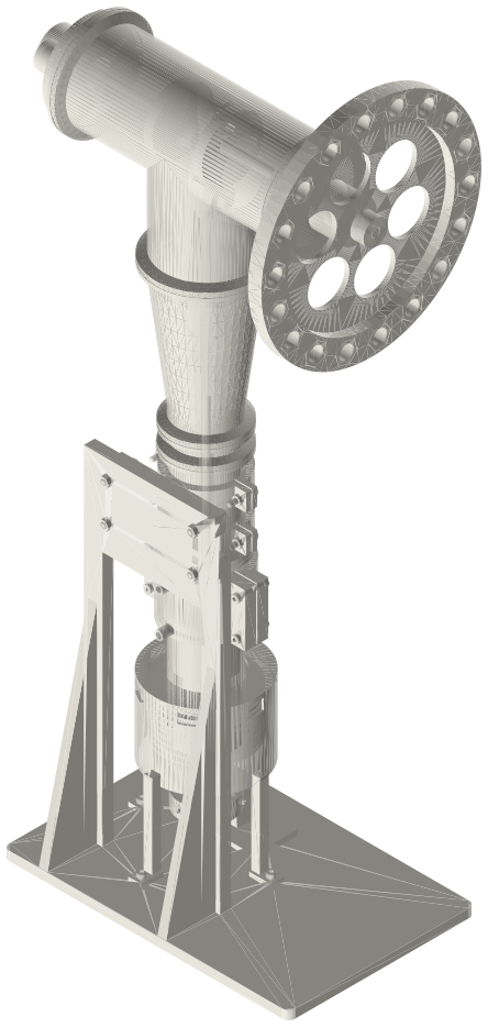
Tri-clamp horizontal gamma generator, 2 in,…The classic desk Stirling generator in tri-clamp, built for power: a horizontal …Tri-clamp walking-beam gamma generator, 2 in,…The classic desk walking-beam Stirling in tri-clamp: a standard 2 in tee with th…Tri-clamp charged beta, 2 inA standing beta that holds a charge: the same hot spool, liner, regenerator and …Tri-clamp twin walking-beam gamma generator, 2…Two walking-beam tee units side by side on one crank, a quarter turn apart: each…You might also need
Questions
Why slots and not the plain annular gap?
A plain 0.5 mm gap on a Ø48 bore has about a fifth of the wetted area; with air at a charge the cooler then runs far above the water temperature.
What does the press fit do?
It is the heat path from the spool wall into the fins. The engine numbers assume 5000 W/(m²·K) at the fin tips.