 Xem Studiomeasured geometry
Library › Stirling engines › Tri-clamp engine parts ·
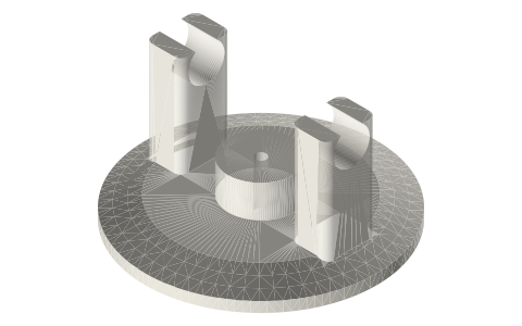
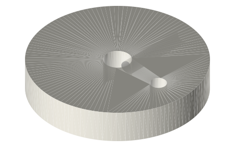
Tri-clamp crank head: ISO 2852 cap with Ø3 rod bore and two 623 towers, 1.5, 2 and 3 in
What tri-clamp head carries the displacer rod and a crankshaft on the cap itself? · Hardware · basis: ISO 2852 cap face; Ø3 run bore for the displacer rod; two 623 bearing pockets (Ø10) on a Ø3 crank axis 30 mm above the face
Long Earth Society build part. The displacers and heads the LES tri-clamp engines are built from. The engines
Exact dimensions. Every file is drawn at true size with no printing tolerance. The holes and pins that meet another part are listed below under Mating features, with the fit each joint needs; open those by your printer's or process's clearance before making the part. Mating features
- sizes
- 3 in table
Notes
- An ISO 2852 end cap that carries both the displacer rod and a small crankshaft, so the drive sits right on the cylinder.
- On centre: a Ø18 × 9 boss with a Ø3 bore straight through for the Ø3 displacer rod (run fit); the bore is the rod guide and the clearance seal.
- Two towers 10 × 14 × 28 mm stand on the back of the 6 mm cap, centred ±(C3/2 − 11) from the axis (±14.25 / ±21.0 / ±34.5 mm for 1.5 / 2 / 3 in), each with a Ø10 pocket for a 623 bearing; the Ø3 crankshaft axis is 30 mm above the face, 24 mm above the cap's back.
- The overall height is 34 mm; flange Ø50.5 / 64.0 / 91.0.
Sizes
| size_in | flange_od_mm | rod_bore_mm | tower_centres_mm | bearing | crank_axis_above_face_mm |
|---|---|---|---|---|---|
| 1.5 | 50.5 | 3 | 28.5 | 623 (Ø10) | 30 |
| 2 | 64.0 | 3 | 42.0 | 623 (Ø10) | 30 |
| 3 | 91.0 | 3 | 69.0 | 623 (Ø10) | 30 |
Mating features
Drawn at the exact size. Open press, slide, run and socket features by your process's clearance; leave designed gaps and clamp fits as drawn.
| feature | exact | mates with | fit | files |
|---|---|---|---|---|
| bearing pockets | Ø10 | 623 bearing | press | head-crank-* |
| head faces | ISO 2852 | ferrule face + Type B gasket | clamp | head-* |
| rod-gland bore | Ø3 × 13.4 (through cap and Ø18 boss) | Ø3 displacer rod | run | head-crank-* |
Where the files are
Other publishers' files are linked, not hosted. "verify" = check the license at the link before commercial use.
| Long Earth Society | Tri-clamp Stirling engine builds | web, video | LES site |
| James R. Senft | An Introduction to Low Temperature Differential Stirling Engines (displacer and gap design) | book | Moriya Press verify |
| Wikipedia | Stirling engine | web | CC BY-SA 4.0 (text) |
Free files
★ Free files 3 parts. Generated by Xem Studio from the standard; threads are plain cylinders at major diameter. CC BY 4.0. index.json
| head-crank-1.5in | 1.5 in ISO 2852 cap: clearance-seal rod gland (Ø3 bore straight through the cap and its Ø18 boss, 13.4 mm long, for the Ø3 rod; no O-ring) and two 623 bearing towers for a Ø3 crankshaft 24 mm above the cap | STEP · STL |
| head-crank-2in | 2 in ISO 2852 cap: clearance-seal rod gland (Ø3 bore straight through the cap and its Ø18 boss, 13.4 mm long, for the Ø3 rod; no O-ring) and two 623 bearing towers for a Ø3 crankshaft 24 mm above the cap | STEP · STL |
| head-crank-3in | 3 in ISO 2852 cap: clearance-seal rod gland (Ø3 bore straight through the cap and its Ø18 boss, 13.4 mm long, for the Ø3 rod; no O-ring) and two 623 bearing towers for a Ø3 crankshaft 24 mm above the cap | STEP · STL |
Plain text: sheet.txt · JSON: /api/geometry?object=tri-clamp-crank-head
How it fits
Goes in or on
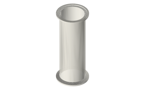 Tri-clamp spool, 1.5 and 2 inchISO 2852 face on the cold-end ferrule
Connects to
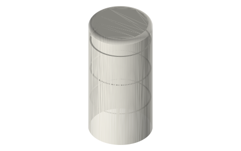 Tri-clamp displacerØ3 rod through the Ø3 bore
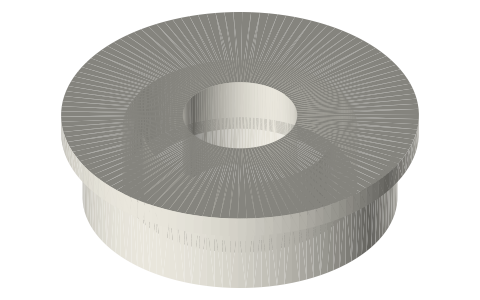 Ball bearings, 683 to 6210 and flanged F6xx623 (3 × 10 × 4) in each Ø10 pocket
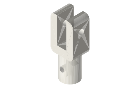 Rod clevises for a Ø2 or Ø3 rod or a Ø5 tube, 5…Ø3-bore crank discs and rod clevis on the Ø3 shaft and rod
Also needed
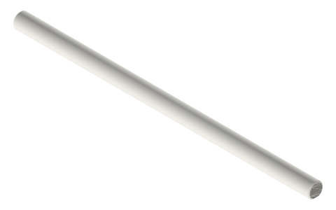 Crankshafts Ø3, Ø5 and Ø8 with full-length D-flatØ3 crankshaft and Ø3 displacer rod
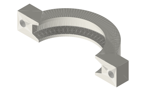 Tri-clamp clamp, two-boltclamp and gasket on the face
You might also need
Questions
How do I seal the displacer rod through a tri-clamp cap?
With a clearance seal: the crank head has a Ø3 bore straight through its Ø18 × 9 boss, and the Ø3 rod runs in it with no O-ring.
How high is the crankshaft on the crank head?
The Ø3 crank axis is 30 mm above the sealing face (24 mm above the cap's back), in two 623 bearings.
How far apart are the crank-head towers?
28.5 mm centre to centre on 1.5 in, 42.0 on 2 in, 69.0 on 3 in.