 Xem Studiomeasured geometry
Library › Stirling engines › Tri-clamp engine parts ·
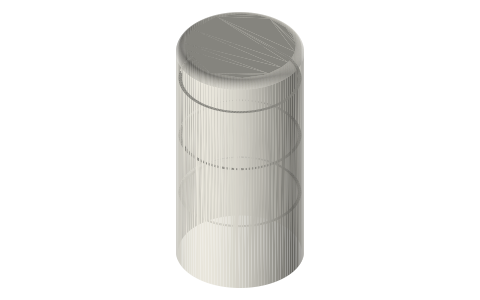
Tri-clamp displacer: Ø33.6, Ø46 and Ø70.9 for 1.5, 2 and 3 in spools
What size displacer fits a 2 inch tri-clamp spool? · Hardware · basis: 16 ga ASME BPE tube bores (1.5 in 34.8, 2 in 47.5, 3 in 72.9 mm) minus a designed radial gap of 0.6 / 0.75 / 1.0 mm (Senft, low-temperature-difference air engines)
Long Earth Society build part. The displacers and heads the LES tri-clamp engines are built from. The engines
Exact dimensions. Every file is drawn at true size with no printing tolerance. The holes and pins that meet another part are listed below under Mating features, with the fit each joint needs; open those by your printer's or process's clearance before making the part. Mating features
- sizes
- 9 in table
Notes
- The displacer is a closed cylinder that runs in the spool bore with a designed radial gap: 0.6 mm in the 1.5 in spool (Ø33.6 in Ø34.8), 0.75 mm in the 2 in (Ø46.0 in Ø47.5), 1.0 mm in the 3 in (Ø70.9 in Ø72.9). The gap is part of the design and is drawn as is.
- Lengths: 1.5 in 50 / 75 / 100, 2 in 60 / 90 / 120, 3 in 80 / 120 / 160 mm. Each length comes two ways: a hollow shell (1 mm wall, closed rounded end, 1.2 mm internal rings every 25 mm) with its end cap, and a solid body of the same diameter and length with a Ø3 centre hole and two 0.6 mm slots crossing on the axis through the full length, so the file is four quarter-segments around the centre hole.
- The shell's end cap has a spigot Ø(D − 2) × 3 that enters the shell, a Ø D × 1.5 flange, and a Ø16 × 6 boss with the Ø3 rod hole and a Ø2.5 radial hole for an M3 grub at 8 mm; the cap stands 10.5 mm overall. One cap file per spool size serves every length.
- The Ø3 rod is the displacer rod: it leaves through the displacer head or crank head on the cold end. Every hole that meets another part is in the Mating features table.
Sizes
| spool_in | bore_mm | displacer_od_mm | length_mm | radial_gap_mm |
|---|---|---|---|---|
| 1.5 | 34.8 | 33.6 | 50 | 0.6 |
| 1.5 | 34.8 | 33.6 | 75 | 0.6 |
| 1.5 | 34.8 | 33.6 | 100 | 0.6 |
| 2 | 47.5 | 46.0 | 60 | 0.75 |
| 2 | 47.5 | 46.0 | 90 | 0.75 |
| 2 | 47.5 | 46.0 | 120 | 0.75 |
| 3 | 72.9 | 70.9 | 80 | 1.0 |
| 3 | 72.9 | 70.9 | 120 | 1.0 |
| 3 | 72.9 | 70.9 | 160 | 1.0 |
Mating features
Drawn at the exact size. Open press, slide, run and socket features by your process's clearance; leave designed gaps and clamp fits as drawn.
| feature | exact | mates with | fit | files |
|---|---|---|---|---|
| displacer OD in the spool bore | bore − 2 × 0.6 / 0.75 / 1.0 | tri-clamp-spool bore | designed | displacer-* |
| cap spigot in the shell | shell bore | displacer shell | slide | displacer-cap-* |
| cap rod hole | Ø3 | Ø3 displacer rod (M3 grub) | slide | displacer-cap-* |
| cap grub hole | Ø2.5 | M3 tap drill | designed | displacer-cap-* |
| displacer-body rod bore | Ø3 | Ø3 displacer rod | slide | displacer-body-* |
Where the files are
Other publishers' files are linked, not hosted. "verify" = check the license at the link before commercial use.
| Long Earth Society | Tri-clamp Stirling engine builds | web, video | LES site |
| James R. Senft | An Introduction to Low Temperature Differential Stirling Engines (displacer and gap design) | book | Moriya Press verify |
| Wikipedia | Stirling engine | web | CC BY-SA 4.0 (text) |
Free files
★ Free files 27 parts. Generated by Xem Studio from the standard; threads are plain cylinders at major diameter. CC BY 4.0. index.json
| displacer-shell-1.5in-50 | 1.5 in shell displacer Ø33.6 × 50 for the Ø34.8 bore (0.6 mm radial gap), 1 mm wall, internal rings every 25 mm, closed rounded end | STEP · STL |
| displacer-cap-1.5in | 1.5 in displacer end cap with Ø3 rod boss and M3 grub (Ø2.5 tapped) at 8 mm; one per displacer | STEP · STL |
| displacer-body-1.5in-50 | 1.5 in solid displacer body Ø33.6 × 50 with a Ø3 rod bore on the axis | STEP · STL |
| displacer-shell-1.5in-75 | 1.5 in shell displacer Ø33.6 × 75 for the Ø34.8 bore (0.6 mm radial gap), 1 mm wall, internal rings every 25 mm, closed rounded end | STEP · STL |
| displacer-cap-1.5in | 1.5 in displacer end cap with Ø3 rod boss and M3 grub (Ø2.5 tapped) at 8 mm; one per displacer | STEP · STL |
| displacer-body-1.5in-75 | 1.5 in solid displacer body Ø33.6 × 75 with a Ø3 rod bore on the axis | STEP · STL |
| displacer-shell-1.5in-100 | 1.5 in shell displacer Ø33.6 × 100 for the Ø34.8 bore (0.6 mm radial gap), 1 mm wall, internal rings every 25 mm, closed rounded end | STEP · STL |
| displacer-cap-1.5in | 1.5 in displacer end cap with Ø3 rod boss and M3 grub (Ø2.5 tapped) at 8 mm; one per displacer | STEP · STL |
| displacer-body-1.5in-100 | 1.5 in solid displacer body Ø33.6 × 100 with a Ø3 rod bore on the axis | STEP · STL |
| displacer-shell-2in-60 | 2 in shell displacer Ø46 × 60 for the Ø47.5 bore (0.75 mm radial gap), 1 mm wall, internal rings every 25 mm, closed rounded end | STEP · STL |
| displacer-cap-2in | 2 in displacer end cap with Ø3 rod boss and M3 grub (Ø2.5 tapped) at 8 mm; one per displacer | STEP · STL |
| displacer-body-2in-60 | 2 in solid displacer body Ø46 × 60 with a Ø3 rod bore on the axis | STEP · STL |
| displacer-shell-2in-90 | 2 in shell displacer Ø46 × 90 for the Ø47.5 bore (0.75 mm radial gap), 1 mm wall, internal rings every 25 mm, closed rounded end | STEP · STL |
| displacer-cap-2in | 2 in displacer end cap with Ø3 rod boss and M3 grub (Ø2.5 tapped) at 8 mm; one per displacer | STEP · STL |
| displacer-body-2in-90 | 2 in solid displacer body Ø46 × 90 with a Ø3 rod bore on the axis | STEP · STL |
| displacer-shell-2in-120 | 2 in shell displacer Ø46 × 120 for the Ø47.5 bore (0.75 mm radial gap), 1 mm wall, internal rings every 25 mm, closed rounded end | STEP · STL |
| displacer-cap-2in | 2 in displacer end cap with Ø3 rod boss and M3 grub (Ø2.5 tapped) at 8 mm; one per displacer | STEP · STL |
| displacer-body-2in-120 | 2 in solid displacer body Ø46 × 120 with a Ø3 rod bore on the axis | STEP · STL |
| displacer-shell-3in-80 | 3 in shell displacer Ø70.9 × 80 for the Ø72.9 bore (1.0 mm radial gap), 1 mm wall, internal rings every 25 mm, closed rounded end | STEP · STL |
| displacer-cap-3in | 3 in displacer end cap with Ø3 rod boss and M3 grub (Ø2.5 tapped) at 8 mm; one per displacer | STEP · STL |
| displacer-body-3in-80 | 3 in solid displacer body Ø70.9 × 80 with a Ø3 rod bore on the axis | STEP · STL |
| displacer-shell-3in-120 | 3 in shell displacer Ø70.9 × 120 for the Ø72.9 bore (1.0 mm radial gap), 1 mm wall, internal rings every 25 mm, closed rounded end | STEP · STL |
| displacer-cap-3in | 3 in displacer end cap with Ø3 rod boss and M3 grub (Ø2.5 tapped) at 8 mm; one per displacer | STEP · STL |
| displacer-body-3in-120 | 3 in solid displacer body Ø70.9 × 120 with a Ø3 rod bore on the axis | STEP · STL |
| displacer-shell-3in-160 | 3 in shell displacer Ø70.9 × 160 for the Ø72.9 bore (1.0 mm radial gap), 1 mm wall, internal rings every 25 mm, closed rounded end | STEP · STL |
| displacer-cap-3in | 3 in displacer end cap with Ø3 rod boss and M3 grub (Ø2.5 tapped) at 8 mm; one per displacer | STEP · STL |
| displacer-body-3in-160 | 3 in solid displacer body Ø70.9 × 160 with a Ø3 rod bore on the axis | STEP · STL |
Plain text: sheet.txt · JSON: /api/geometry?object=tri-clamp-displacer
How it fits
Parts that fit it
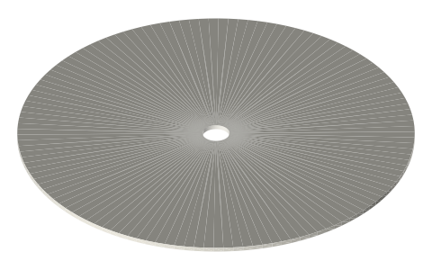 Regenerator matrix disc Ø44 / Ø32 × 0.5 mmmatrix in the regenerative displacer's slots
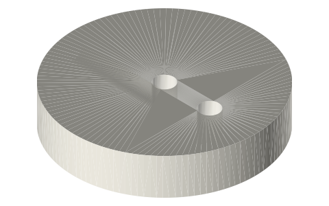 Crank discs Ø30 for a Ø3 crankshaft, 10 to 20 mm…on the crank head's Ø3 shaft between the 623 towers
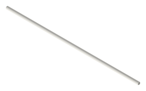 Displacer rods Ø2 × 60, 78, 100 and 180, Ø3 ×…Ø3 rod in the displacer cap socket and the head's Ø3 bore
Goes in or on
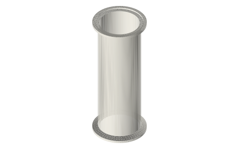 Tri-clamp spool, 1.5 and 2 inchØ46 displacer in the Ø47.5 bore, 0.75 mm radial gap
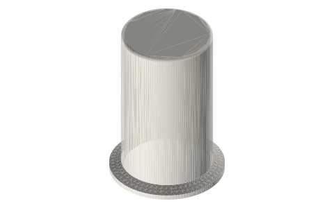 Tri-clamp cupssame 47.5 bore with the hot end closed
Connects to
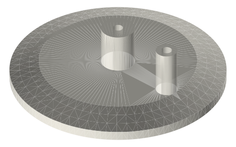 Tri-clamp displacer headØ3 rod from the cap through the head's Ø3 bore
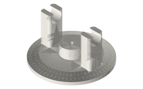 Tri-clamp crank headØ3 rod through the crank head to a crank
Alternatives
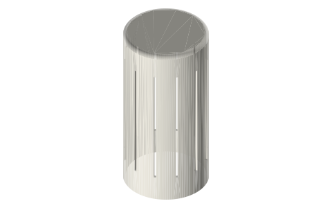 Tri-clamp regenerative displacersingle-spool engine with the regenerator in the gap
Also needed
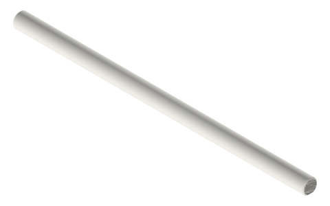 Crankshafts Ø3, Ø5 and Ø8 with full-length D-flatØ3 displacer rod
In these build lists
Gamma Stirling, 2 in tri-clampHot spool with a shell displacer, a crank head that carries the crankshaft, the …Free-piston Stirling, 2 in tri-clampNo crank: piston and displacer each hang on a stack of spiral flexures, with a t…Tri-clamp tee diaphragm gamma, 2 inA tea-light gamma in 2 in tri-clamp: displacer in a 3 in spool, a short-outlet t…Questions
What diameter displacer fits a 2 inch tri-clamp spool?
Ø46.0 mm in the Ø47.5 bore, a 0.75 mm radial gap, in 60, 90 or 120 mm lengths.
How much gap is there between the displacer and the spool?
0.6 mm radial in the 1.5 in spool, 0.75 mm in the 2 in, 1.0 mm in the 3 in: a designed gap, drawn at that size.
How does the rod attach to the displacer?
Through the end cap: a Ø3 hole in a Ø16 × 6 boss, held by an M3 grub in a Ø2.5 radial hole 8 mm up the cap.
Is there a solid version?
Yes: each length also comes as one solid body of the same diameter and length (Ø × L), with a Ø3 centre hole and two 0.6 mm cross slots.