 Xem Studiomeasured geometry
Library › Electronic components › Connectors ·
IEC 60320 appliance couplers: C13 / C14, C5 / C6, C7 / C8, C15 / C16, C17 / C18, C19 / C20, C21 to C24 (pin spacing, ratings, snap-in panel numbers)
What is the pin spacing of a C13 / C14 and a C19 / C20, what do the C-numbers mean, and what panel cutout does an inlet need? · Standard part · basis: IEC 60320-1 as tabulated by Wikipedia and Interpower's coupler sheet, plus Interpower, Farnell and Schurter datasheet text for panel numbers; numbers only
Also called: iec c13 c14 dimensions, c13 c14 pin spacing, c19 vs c13, c20 inlet cutout, iec c14 inlet panel cutout, iec 60320 c5 c6 cloverleaf, c7 c8 figure 8 connector, c15 c16 hot condition, c13 vs c15, c17 c18 connector, kettle lead c15, iec 60320 coupler chart, c14 inlet hole size, iec 320 c20
Exact dimensions. Every file is drawn at true size with no tolerance added. The holes and pins that meet another part are listed below under Mating features, with the fit each joint needs; open those by your process's clearance before making the part. Mating features
- sizes
- 17 in table
Notes
- IEC 60320-1 appliance couplers come in pairs: a connector on a cord (C13) and an inlet on the equipment (C14). The pin-spacing column is the centre-to-centre spacing between the line and neutral pins: for the earthed pairs it is given horizontal (H) and vertical (V) as Wikipedia prints it from the standard. C13 / C14 is 14 mm × 4 mm, C19 / C20 is 13 mm × 8 mm, C5 / C6 (cloverleaf) 10 mm × 4.5 mm and C7 / C8 (figure 8) 8.6 mm.
- The letters A to L are the interconnection couplers (a plug connector on the equipment and an appliance outlet on the cord, the same pin layout as the C-pair beside them in the table above). Interpower's sheet pairs C5 / C6 with A, B; C7 / C8 with C, D; C13 / C14 with E, F; C17 / C18 with G, H; C19 / C20 with I, J; C23 / C24 with K, L and does not map the others. Wikipedia's table gives the same pin spacing for the pairs (A / B 10 × 4.5, C / D 8.6, E / F 14 × 4, G / H 14, I / J 13 × 8, K / L 13). M to R (high-temperature interconnection types from a 2022 amendment) are not tabulated here.
- The 10 A international ratings are 15 A in North America (UL / CSA 60320-3) and the 16 A types are 20 A there; the sheet gives all couplers at 250 V AC maximum. C3 / C4 and C11 / C12 are withdrawn.
- Panel cutouts: the numbers printed as text by makers. They disagree with each other (20 × 27.5 on Interpower; 28.8 or 29.6 × 19.4 on one Farnell-hosted datasheet; the panel-cutouts page has 27.5 × 19.5 and notes 27.4 × 19.4 on some drawings), so no single cutout gauge is drawn. The cutout depends on the maker and the mounting (snap-in or screw), so use the one on the datasheet of the inlet you buy. The C20 and C8 cutout numbers are in the Schurter drawings but the text read does not say which number is which.
- Left out: pin width and thickness, shell outlines and the slot positions of the connectors: they are in the paid IEC 60320-1 and were not published in the sources read. No files are drawn for that reason.
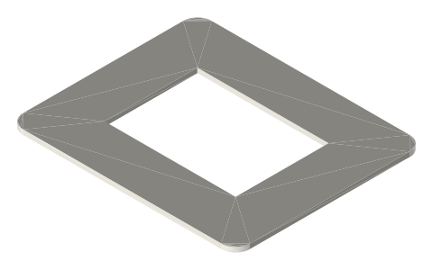
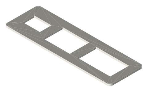
- The C14 inlet and C13 outlet cutouts with their screw holes are on the page panel-cutouts.
IEC 60320 appliance couplers: C13 / C14, C5 / C6, C7 / C8, C15 /… size chart
| connector / inlet | max current (A) | max pin temperature (°C) | earth contact | polarised | appliance class | pin spacing, centres (mm) | interconnection pair beside it (Interpower) |
|---|---|---|---|---|---|---|---|
| C1 (connector) / C2 (inlet) | 0.2 | 70 | no | no | II | 6.6 | not stated |
| C3 (connector) / C4 (inlet) | 2.5 | 70 | no | yes | II | 10 | not stated |
| C5 (connector) / C6 (inlet) | 2.5 | 70 | yes | yes | I | 10 (H), 4.5 (V) | A / B |
| C7 (connector) / C8 (inlet) | 2.5 | 70 | no | no | II | 8.6 | C / D |
| C9 (connector) / C10 (inlet) | 6 | 70 | no | no | II | 10 | not stated |
| C11 (connector) / C12 (inlet) | 10 | 70 | no | yes | II | 10 | not stated |
| C13 (connector) / C14 (inlet) | 10 | 70 | yes | yes | I | 14 (H), 4 (V) | E / F |
| C15 (connector) / C16 (inlet) | 10 | 120 | yes | yes | I | 14 (H), 4 (V) | not stated |
| C15A (connector) / C16A (inlet) | 10 | 155 | yes | yes | I | 14 (H), 4 (V) | not stated |
| C17 (connector) / C18 (inlet) | 10 | 70 | no | yes | II | 14 | G / H |
| C19 (connector) / C20 (inlet) | 16 | 70 | yes | yes | I | 13 (H), 8 (V) | I / J |
| C21 (connector) / C22 (inlet) | 16 | 155 | yes | yes | I | 13 (H), 8 (V) | not stated |
| C23 (connector) / C24 (inlet) | 16 | 70 | no | yes | II | 13 | K / L |
| panel cutout: C14, C16, C18 snap-in inlet | 20 × 27.5 mm | panel 1.0, 1.5, 2.0, 3.0 mm | - | - | - | - | Interpower; the same cutout for all three |
| panel cutout: C14 / C18 snap-in inlet (Farnell-hosted datasheet) | 28.8 × 19.4 mm for 0.8 to 1.5 mm panels; 29.6 × 19.4 mm for 1.6 to 2.0 mm panels | panel 0.8 to 2.0 mm | - | - | - | - | maker not named in the text read; two bands |
| panel cutout: C20 snap-in inlet (Schurter 1624) | not read (the drawing's numbers are not labelled in the text) | panel 1.5, 2.0, 2.5 mm (the order code also allows 3.0) | - | - | - | - | Schurter data sheet |
| panel cutout: C8 snap-in inlet (Schurter 2578) | not read (cutout numbers are not labelled in the text) | panel 1.5, 2.0, 2.5, 3.0 mm; a 1.0 mm variant has its own cutout | - | - | - | - | Schurter data sheet |
Mating features
Drawn at the exact size. Open press, slide, run and socket features by your process's clearance (tolerances by process); leave designed gaps and clamp fits as drawn.
| feature | exact | mates with | fit | files |
|---|---|---|---|---|
| C13 connector pins | 14 mm (H) × 4 mm (V) centres, 10 A (15 A NA), 70 °C | C14 inlet (same spacing) | designed | all |
| C19 connector pins | 13 mm (H) × 8 mm (V) centres, 16 A (20 A NA), 70 °C | C20 inlet | designed | all |
| C5 connector pins | 10 mm (H) × 4.5 mm (V) centres, 2.5 A | C6 inlet (cloverleaf) | designed | all |
| C7 connector pins | 8.6 mm centres, 2.5 A, unearthed | C8 inlet (figure 8) | designed | all |
| C15 connector pins | 14 mm (H) × 4 mm (V) centres, 120 °C | C16 inlet | designed | all |
| C17 connector pins | 14 mm centres, 10 A, unearthed | C18 inlet | designed | all |
Where the files are
Other publishers' files are linked, not hosted. "verify" = check the license at the link before commercial use.
Xem scan
File coming
No downloadable true-size file yet: the published figures do not fix the whole shape, and Xem never guesses a number. A measured scan is planned; request it and it moves up.
https://xemstudio.com/mcp to Claude, ChatGPT, Cursor or any MCP client (free, no account, one minute) and it can look up exact sizes, mating fits and free STEP/STL from every chat.Plain text: sheet.txt · JSON: /api/geometry?object=iec-60320-appliance-couplers-c13-c14-c19-c20
Fits with
Questions
What is the difference between C13 and C19?
C13 / C14 is rated 10 A (15 A North America) with pins 14 mm × 4 mm; C19 / C20 is 16 A (20 A North America) with pins 13 mm × 8 mm.
What does a C14 inlet mate with?
A C13 connector. The C16 inlet (120 °C pins) is the pair of the C15 connector.
What is a C7 / C8 connector?
The unearthed 2.5 A figure-8 pair, pin spacing 8.6 mm, class II.
What cutout does a C14 snap-in inlet need?
20 × 27.5 mm for Interpower's inlets, 1.0 to 3.0 mm panels; other makers print other numbers, so check the datasheet.