 Xem Studiomeasured geometry
Library › Electronics › Generators & alternators ·
Linear alternator module, 2 in, closed (sealed bounce space, chargeable)
One standard linear alternator that clamps in line on any 2 in sanitary device: a Ø48 clearance-seal piston on two spiral leaves, 40 magnets, the stator and coil outside the wall, ISO 2852 faces at both ends. Built once and moved between engines, so their power can be compared.
Ø48 piston ±5 mm (±6 max) · moving mass 865 g · leaves 8851 N/m · Bl 28.8 N/A · coil 3.40 Ω, ≈25 mH · f₀ 16 Hz open, 19 Hz on 1 bar air, 36 Hz on 10 bar helium · 147.0 mm face to face · relief 15 bar g
Exact dimensions. Every part is drawn at true size with no printing tolerance; each part's page lists its mating features and the fit each joint needs, so open those by your process's clearance before making the parts.
Long Earth Society build part. Complete parts list. The engines
106 parts, every one a file here · all STL URLs · Markdown · tick lines as you go (saved in this browser)
| subsystem | object | parts | qty | note | |
|---|---|---|---|---|---|
| None | Linear alternator module spools | spool-2in-42mm-bored-48.00 STEP · STL | 1 | face A (to the engine) and the piston's cylinder | |
| None | 2 in × 3 in spool with the bore finished | spool-2in-3in-bored-48.00 STEP · STL | 1 | the alternator section: magnet carrier inside, stator outside | |
| None | Linear alternator module spools | spool-2in-25.4mm STEP · STL | 1 | face B end: leaf 2's hub travel | |
| None | Tri-clamp flexure leaf | leaf-2in-piston-t0.8 STEP · STL | 2 | choose one leaf set, A (standard 0.8): joints 1 and 2; leaf 2 turned over (opposite hand) | |
| None | Tri-clamp half gasket for a clamped leaf | leaf-half-gasket-2in-w0.45 STEP · STL | 4 | choose one leaf set, A (standard 0.8): two per leaf, beads outward | |
| None | Linear alternator module tuning parts | leaf-2in-piston-t0.5 STEP · STL | 2 | choose one leaf set, B (soft 0.5, tuning): joints 1 and 2 in place of the 0.8 leaves; leaf 2 turned over | |
| None | Tri-clamp half gasket for a clamped leaf | leaf-half-gasket-2in-w0.6 STEP · STL | 4 | choose one leaf set, B (soft 0.5, tuning): two per soft leaf, beads outward | |
| None | Linear alternator module mover | la-piston-cup-48x24 STEP · STL | 1 | in the 42 bored spool, crown toward face A | |
| None | Linear alternator module mover | la-tube-rod-18x14x108.15 STEP · STL | 1 | pressed into the cup's socket; through both leaves | |
| None | Linear alternator module mover | la-magnet-carrier-47x56 STEP · STL | 1 | pressed on the tube rod, centred under the stator | |
| None | Neodymium disc magnets | magnet-12x3 STEP · STL | 40 | 4 rows of 10 in the carrier, faces out: S, N, N, S from face A | |
| None | Leaf hub collars | fpse-collar-18x28 STEP · STL | 4 | either side of each leaf's hub on the tube rod | |
| None | Set screws (grub screws) | set-m3x4 STEP · STL | 4 | one grub per collar | |
| None | Moving-magnet linear alternator stator o | fpse-stator-pack-43deg STEP · STL | 8 | round the 3 in bored spool at the magnets' centre | |
| None | Moving-magnet linear alternator stator o | fpse-bobbin-65 STEP · STL | 1 | between the teeth; slid over the spool's flange first | |
| None | Moving-magnet linear alternator stator o | fpse-coil-300t STEP · STL | 1 | 300 turns of 0.71 mm enamelled wire on the bobbin; the leads leave through the housing | |
| None | Moving-magnet linear alternator stator o | fpse-stator-housing-half STEP · STL | 2 | clamp the packs onto the tube | |
| None | Socket head cap screws | shcs-m4x20 STEP · STL | 4 | stator housing ears | |
| None | Hex nuts | nut-m4 STEP · STL | 4 | stator housing ears | |
| None | High-pressure bolted sanitary clamp | hp-clamp-2in | 4 | bought: joints 1 and 2, face B (cap or next device) and face A (to the engine); rated above the 15 bar gauge relief setting | |
| None | Tri-clamp gasket | tc-gasket-2in STEP · STL | 2 | Type B at face A (to the engine) and face B (under the cap); rated above the relief setting | |
| None | Tri-clamp port cap | port-cap-2in-4x-npt18 STEP · STL | 1 | closes face B (the bounce space): fill valve, pressure gauge, relief valve, and a plug or pressure transducer; off when face B clamps into a loop | |
| None | NPT male thread envelopes 1/8 to 1 in (A | npt-1-8-male STEP · STL | 4 | the 1/8 NPT stems of the fill valve, gauge, relief valve and plug (bodies are the builder's choice) | |
| None | Linear alternator module tuning parts | la-mass-disc-41x26x4 STEP · STL | 4 | optional (tuning): add-on mass discs on the crown inside the cup, 0 to 4 | |
| None | Socket head cap screws | shcs-m3x20 STEP · STL | 3 | optional (tuning): hold 4 discs (3 × M3 × 16 for 3, × 12 for 2, × 8 for 1) | |
| None | Linear alternator module | 1 | load resistor: non-inductive, power rated above the expected output; value on the datasheet: bought, not drawn | ||
| None | Linear alternator module | 1 | series capacitor: non-polar, C = 1/(ω² L) for the running frequency (datasheet), rated above the voltage across it: bought, not drawn |
Assembled engine
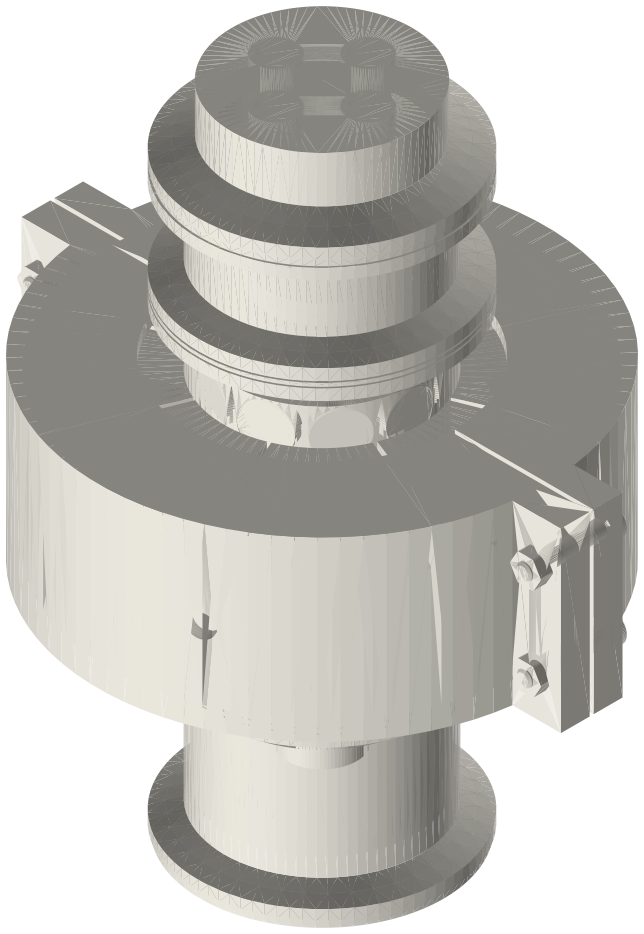
A clamp-in linear alternator module in 2 in tri-clamp fittings: three plain spools (42 mm bored, 3 in bored, 25.4 mm) with ISO 2852 faces at both ends, a 48 mm clearance-seal piston and 40-magnet carrier sprung on two spiral leaves clamped in the inner joints, the laminated stator and coil outside the wall, face B closed by a four-port cap; about 140 × 116 × 170 mm.
Assembly STEP (2.9 MB) · STL (4.0 MB) · 87 parts
Build order
- Magnets into the carrier (rows S, N, N, S from the end that faces A), carrier pressed on the tube rod at its drawn place, tube pressed into the cup's socket. Mass discs on the crown now if the tuning needs them.
- Coil on its bobbin over the 3 in bored spool's flange to the middle; eight stator packs round the tube at the coil; housing halves with 4 × M4 × 20. Leads out through the housing's hole.
- 42 bored spool face A down. Mover in, crown down, until the crown is 9.00 below face A (depth gauge). Collar on the tube, half gasket (bead down), leaf 1, half gasket (bead up), the 3 in spool with its stator, collar; clamp joint 1; grubs.
- Collar, half gasket, leaf 2 turned over, half gasket, the 25.4 spool, collar; clamp joint 2; check the crown is still at 9.00 and the mover moves freely ±6 by hand from face A.
- Face B: Type B gasket, four-port cap, clamp; fill valve, gauge, relief valve, plug. Face A: Type B gasket and clamp onto the engine. Load resistor and capacitor on the leads before the engine runs.
Questions
Why one standard unit?
Moved between engines with the same load, it turns 'which engine is better' into a measurement: the unit's own mass, springs, losses and Bl are the same every time and are on the datasheet.
What engines does it fit?
Anything with a 2 in ferrule carrying a pressure wave: a free-piston Stirling hot end, a thermoacoustic loop, ring or standing-wave engine. On a ring or loop, face B clamps to the next part instead of the cap.
What must the clamps and gaskets be rated for?
Above the 15 bar gauge relief at their temperature. High-pressure bolted 2 in clamps are published at 1000 psi (69 bar) at 70–75 °F.
Where is the electricity?
Two leads from the coil outside the vessel: no wire passes the pressure boundary. Always connect the load before the engine runs.
Agents: each row's object has /api/geometry?object=slug and the MCP tool get_free_files; the STL list above is every part.
JSON: /api/geometry?object=list-linear-alternator-module-2in-closed