 Xem Studiomeasured geometry
Tri-clamp cross diaphragm gamma, 2 in
A fast gamma in 2 in tri-clamp: a hot cap and short spool over a torch, a cross as the sealed crankcase with the crank inside it, a diaphragm on top and a thin crankshaft out through a long bore to the flywheel.
Diaphragm 2 in at 12 mm: 11.3 mL swept · displacer Ø46 × 60 at 12 mm: 19.9 mL swept · dead volume 68.1 mL · swept / dead 0.166
Exact dimensions. Every part is drawn at true size with no printing tolerance; each part's page lists its mating features and the fit each joint needs, so open those by your process's clearance before making the parts.
49 parts, every one a file here · all STL URLs · Markdown · tick lines as you go (saved in this browser)
| subsystem | object | parts | qty | note | |
|---|---|---|---|---|---|
| None | Frame for the 2 in tri-clamp cross diaph | cross-engine-frame-2in STEP · STL | 1 | base, wall, gussets | |
| None | Torch stand for a horizontal tri-clamp h | torch-stand-40 STEP · STL | 1 | on the base under the hot cap, post toward the front | |
| None | Socket head cap screws | shcs-m4x10 STEP · STL | 2 | torch stand to the base | |
| None | Set screws (grub screws) | set-m4x10 STEP · STL | 3 | centre the torch head in the stand ring | |
| None | Tri-clamp end cap | tc-cap-2in-flat STEP · STL | 2 | hot cap (face up, over the flame) and the +X branch | |
| None | Tri-clamp flat gasket (hot joint | hot-gasket-2in STEP · STL | 1 | hot joint | |
| None | Tri-clamp heat shield washer | heat-shield-2in STEP · STL | 1 | on the hot clamp | |
| None | Tri-clamp spool (two ferrules on a tube) | tc-spool-2in-3in STEP · STL | 1 | hot cylinder with the cap: displacer inside | |
| None | Tri-clamp jacket shell | jacket-half-2in-56 STEP · STL | 2 | band round the hot spool; the fill is the builder's choice | |
| None | Tri-clamp jacket shell | jacket-port-cap STEP · STL | 2 | one per jacket half | |
| None | Socket head cap screws | shcs-m4x30 STEP · STL | 4 | jacket ears | |
| None | Hex nuts | nut-m4 STEP · STL | 6 | jacket ears (4), hanger ears (2) | |
| None | Sanitary clamp crosses (9MP) | cross-2in STEP · STL | 1 | the crankcase: run vertical, branches along the crankshaft | |
| None | Tri-clamp gasket | tc-gasket-2in STEP · STL | 3 | spool–cross, end cap, bearing cap | |
| None | Tri-clamp clamp | clamp-half-2in STEP · STL | 10 | five joints, two halves each | |
| None | Socket head cap screws | shcs-m5x30 STEP · STL | 10 | clamp bolts | |
| None | Hex nuts | nut-m5 STEP · STL | 12 | clamp nuts (10), hanger bar (2) | |
| None | Crankcase insert for a 2 in tri-clamp cr | crankcase-insert-2in STEP · STL | 1 | fills the run; Ø3 displacer-rod guide; crank chamber | |
| None | Branch plugs for a 2 in tri-clamp cross | branch-plug-2in-blind STEP · STL | 1 | end-cap branch | |
| None | Branch plugs for a 2 in tri-clamp cross | branch-plug-2in-bore16 STEP · STL | 1 | bearing-cap branch | |
| None | Tri-clamp bearing cap | bearing-cap-2in-b3 STEP · STL | 1 | −X branch: two 623 seats, Ø3 bore 75.1 long | |
| None | Tri-clamp displacer | displacer-shell-2in-60 STEP · STL | 1 | Ø46 × 60, 0.75 radial gap, 12 stroke | |
| None | Tri-clamp displacer | displacer-cap-2in STEP · STL | 1 | closes the shell, holds the rod | |
| None | Crankshafts Ø3 | crankshaft-3x60 STEP · STL | 1 | displacer rod (Ø3 × 60), through the insert's guide | |
| None | Crankshafts Ø3 | crankshaft-3x44 STEP · STL | 1 | diaphragm rod (Ø3 × 44) | |
| None | Rod clevises for a Ø2 or Ø3 rod or a Ø5 | rod-clevis-3mm STEP · STL | 2 | displacer rod, diaphragm rod | |
| None | Connecting rods 30 to 80 mm centres with | conrod-30 STEP · STL | 2 | diaphragm (in its clevis gap) and displacer (beside its clevis) | |
| None | Ball bearings | bearing-623 STEP · STL | 6 | con-rod eyes (4), bearing cap (2) | |
| None | Inner crank webs for the tri-clamp cross | inner-crank-web-hub-r6 STEP · STL | 1 | on the shaft end | |
| None | Inner crank webs for the tri-clamp cross | inner-crank-web-link-r6 STEP · STL | 1 | on the diaphragm pin; carries the displacer pin | |
| None | Dowel pins | dowel-3x12 STEP · STL | 3 | diaphragm crank pin, displacer crank pin, diaphragm clevis pin | |
| None | Dowel pins | dowel-3x20 STEP · STL | 1 | displacer clevis pin, con-rod beside the clevis | |
| None | Shaft spacers for Ø3 | spacer-3mm-t2 STEP · STL | 1 | on the displacer clevis pin between clevis and con-rod | |
| None | Shaft spacers for Ø3 | spacer-3mm-t1 STEP · STL | 2 | hub web to inner 623; outer 623 to flywheel | |
| None | Metric shafts Ø3 to Ø10 with D-flats and | shaft-3x100 STEP · STL | 1 | crankshaft | |
| None | Flywheels Ø100–Ø200 with hex-nut rim poc | flywheel-100-m8-b3 STEP · STL | 1 | outside the bearing cap, hub toward the cap | |
| None | Hex nuts M8 | nut-m8 STEP · STL | 12 | one in each rim pocket | |
| None | Tri-clamp diaphragm head | diaphragm-head-2in STEP · STL | 1 | on the top of the run: the power diaphragm, rod inward | |
| None | Tri-clamp diaphragm membrane | membrane-2in STEP · STL | 1 | clamped in place of the gasket | |
| None | Tri-clamp diaphragm centre disc and back | diaphragm-disc-2in STEP · STL | 1 | gas side of the membrane, boss inward, carries the rod | |
| None | Tri-clamp diaphragm centre disc and back | diaphragm-backing-2in STEP · STL | 1 | head side of the membrane | |
| None | Socket head cap screws | shcs-m2x8 STEP · STL | 3 | heads on the head side, through backing disc, membrane and centre disc | |
| None | Hex nuts | nut-m2 STEP · STL | 3 | on the centre disc | |
| None | Set screws (grub screws) | set-m3x4 STEP · STL | 5 | grubs: displacer cap, diaphragm disc, two clevises, flywheel | |
| None | Set screws (grub screws) | set-m3x3 STEP · STL | 1 | hub web on the shaft | |
| None | Spool hanger collars | hanger-2in-tab STEP · STL | 1 | on the cross's lower run, bar to the wall | |
| None | Spool hanger collars | hanger-2in-plain STEP · STL | 1 | closes the hanger | |
| None | Socket head cap screws | shcs-m4x20 STEP · STL | 2 | hanger ears | |
| None | Socket head cap screws | shcs-m5x25 STEP · STL | 2 | hanger bar through the wall |
Assembled engine
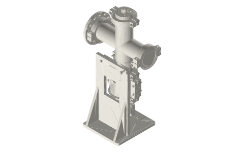
Fast torch-heated gamma Stirling engine in 2 in tri-clamp fittings: hot cap and 3 in spool with a light displacer, a 2 in cross as the sealed crankcase with a two-throw crank inside, a clamped diaphragm on top and a Ø3 shaft out through a long bore to the flywheel, 208 × 150 × 388 mm.
Assembly STEP (2.8 MB) · STL (7.2 MB) · 125 parts
Build order
- Frame on the bench; torch stand on the base with two M4 × 10; torch head in the ring, three M4 set screws.
- Hot cap face up; hot gasket, 3 in spool, clamp; heat shield on the clamp; jacket halves round the spool with four M4 × 30, port caps in.
- Displacer shell and cap with the Ø3 × 60 rod in the cap's grub; displacer into the spool; rod clevis on the rod top.
- Type B gasket, cross (branches along the shaft line), clamp; spool hanger on the lower run, bar to the wall with two M5 × 25.
- Insert down the run over the rod onto the gasket lip; blind branch plug, gasket, end cap, clamp on +X; bored plug, gasket, bearing cap with its two 623s, clamp on −X.
- Shaft in from the flywheel side through the cap; spacer, hub web with its grub; con-rods with their 623s; diaphragm pin through hub web and diaphragm con-rod; link web on the pin with the displacer pin and con-rod; displacer con-rod to its clevis beside the spacer on the Ø3 × 20 pin.
- Diaphragm: backing disc, membrane, centre disc with three M2 × 8 and nuts; Ø3 × 44 rod in the boss; rod clevis on the con-rod with the Ø3 × 12 pin; membrane on the top face, head over it, clamp.
- Spacer and flywheel with its twelve nuts on the shaft outside the cap.
Agents: each row's object has /api/geometry?object=slug and the MCP tool get_free_files; the STL list above is every part.
JSON: /api/geometry?object=list-tri-clamp-cross-diaphragm-gamma