 Xem Studiomeasured geometry
Library › Stirling engines › Free-piston ·
Tri-clamp free-piston kit: flexure head, stack ring, hub collars and piston plug for 1.5, 2 and 3 in spools
How do I hang a tri-clamp piston and displacer on flexure bearings to make a free-piston Stirling engine? · Hardware · basis: Spiral flexure entry (Ø60/80/100 leaves, 3 rim holes, hub Ø13.2/17.6/22); tri-clamp piston entry (-rod variants); Sunpower / NASA layout: displacer rod through the piston, both suspended on planar spring stacks at the cold end
Long Earth Society build part. The connecting parts of the tri-clamp free-piston engine. The engines
- sizes
- 3 in table
Notes
- Layout, cold end outward: hot cup → spool with the displacer and the -rod piston in it → flexure head (clamps on the spool's open ferrule with a stock clamp) carrying stack A on the piston's tube rod → three M3 standoffs → flexure ring carrying stack B on the displacer rod. Nothing touches but the clearance seals: piston in the bore, displacer rod in the piston's bushing.
- Piston side: print the -rod piston, press a dry 3 × 5 × 6 bushing in its crown (graphite-bronze or degreased sintered bronze, no oil), drop the piston plug into the skirt and push the two Ø3 × 16 wrist dowels through bosses and plug legs (the bore retains the dowels). Press a 5 mm K&S brass tube into the plug socket (CA): that is the piston rod. Stack A = hub collar b5 · leaf · hub washer · leaf · hub collar b5 on the tube (Ø100 leaves have a Ø8 hub bore: put the hub-bush-100-b5 on the tube first), rim bolted to the head with the clamp plate and spacer from the flexure entry.
- Displacer side: Ø3 rod from the displacer cap (M3 grub) through the piston bushing, up the inside of the tube, to stack B on the ring: hub collar b3 · leaf · washer · leaf · collar b3, all on the hub-bush b3 so the leaves' Ø5/Ø8 hub bores are centred on the Ø3 rod. Rod length = spool + head + standoffs; cut music wire or drill rod.
- Stack B height sets the displacer phase mass: 30–40 mm standoffs. Tune: each moving assembly resonates at f = (1/2π)√(k/m); the displacer should run 60–90° ahead of the piston, which you get by making the displacer resonance a little above the piston's (stiffer stack or lighter displacer). Measure stack stiffness with weights before cutting steel.
- Power take-off: the linear alternator entry's Ø40 magnet carrier slides on the same 5 mm tube between the head and stack A; the coil annulus sits on the standoffs. Or just watch it run on the printed PETG leaves first.
- Bounce space: with the head open the piston's back side is atmosphere and the engine is a low-pressure demonstrator. For a sealed bounce space put a tri-clamp cup over the whole drive on a longer spool section; the flexure head is then inside the vessel.
- LES: the free-piston test bed in tri-clamp.
Sizes
| spool | bore_mm | flexure_od | hub_mm | tube_rod_mm | displacer_rod_mm | plate_od | plug_pin_z_mm |
|---|---|---|---|---|---|---|---|
| 1.5 | 34.8 | 60 | 13.2 | 5 | 3 | 76 | 17.6 |
| 2 | 47.5 | 80 | 17.6 | 5 | 3 | 96 | 23.5 |
| 3 | 72.9 | 100 | 22.0 | 5 | 3 | 116 | 37.0 |
Where the files are
Other publishers' files are linked, not hosted. "verify" = check the license at the link before commercial use.
| NASA NTRS | Free-piston Stirling convertor flexure bearing development and life testing | US Government work | |
| Long Earth Society | Tri-clamp Stirling engine builds | web, video | LES site |
| Wikipedia | Free-piston engine | web | CC BY-SA 4.0 (text) |
Free files
★ Free files 19 parts. Generated by Xem Studio from the standard; threads are plain cylinders at major diameter. CC BY 4.0. index.json
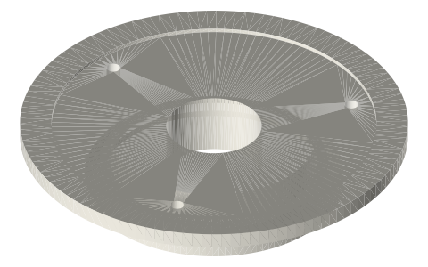
| fp-flexure-head-1.5in | 1.5 in flexure head: ISO 2852 cap face, Ø38.1 pedestal clearing the clamp, Ø76 plate with a Ø60.4 pocket and 3 × M3 on the Ø60 flexure's rim holes; the piston's stack A bolts on it | STEP · STL |
| fp-flexure-ring-60 | Ø76 ring for stack B (displacer rod) on 3 × M3 standoffs above the head | STEP · STL |
| hub-collar-60-b5 | split hub collar Ø13.2 × 5, Ø5.1 bore, M3 pinch: clamps the leaf hub on the 5 mm tube rod (two per stack) | STEP · STL |
| hub-collar-60-b3 | split hub collar Ø13.2 × 5, Ø3.1 bore, M3 pinch: clamps the leaf hub on the Ø3 displacer rod (two per stack) | STEP · STL |
| hub-bush-60-b3 | centring bush Ø4.95 OD × Ø3.1 ID × 14: centres the Ø60 leaves (Ø5 hub bore) on the Ø3 displacer rod; or a 4 mm K&S tube sleeved on the rod | STEP · STL |
| fp-piston-plug-1.5in | 1.5 in piston plug: drops into the open skirt, two Ø3 × 16 wrist dowels through its legs at 17.6 mm retain it, Ø5 tube socket 15 deep, Ø3.4 displacer-rod clearance | STEP · STL |
| fp-flexure-head-2in | 2 in flexure head: ISO 2852 cap face, Ø50.8 pedestal clearing the clamp, Ø96 plate with a Ø80.4 pocket and 3 × M3 on the Ø80 flexure's rim holes; the piston's stack A bolts on it | STEP · STL |
| fp-flexure-ring-80 | Ø96 ring for stack B (displacer rod) on 3 × M3 standoffs above the head | STEP · STL |
| hub-collar-80-b5 | split hub collar Ø17.6 × 5, Ø5.1 bore, M3 pinch: clamps the leaf hub on the 5 mm tube rod (two per stack) | STEP · STL |
| hub-collar-80-b3 | split hub collar Ø17.6 × 5, Ø3.1 bore, M3 pinch: clamps the leaf hub on the Ø3 displacer rod (two per stack) | STEP · STL |
| hub-bush-80-b3 | centring bush Ø4.95 OD × Ø3.1 ID × 14: centres the Ø80 leaves (Ø5 hub bore) on the Ø3 displacer rod; or a 4 mm K&S tube sleeved on the rod | STEP · STL |
| fp-piston-plug-2in | 2 in piston plug: drops into the open skirt, two Ø3 × 16 wrist dowels through its legs at 23.5 mm retain it, Ø5 tube socket 15 deep, Ø3.4 displacer-rod clearance | STEP · STL |
| fp-flexure-head-3in | 3 in flexure head: ISO 2852 cap face, Ø76.2 pedestal clearing the clamp, Ø116 plate with a Ø100.4 pocket and 3 × M3 on the Ø100 flexure's rim holes; the piston's stack A bolts on it | STEP · STL |
| fp-flexure-ring-100 | Ø116 ring for stack B (displacer rod) on 3 × M3 standoffs above the head | STEP · STL |
| hub-collar-100-b5 | split hub collar Ø22 × 5, Ø5.1 bore, M3 pinch: clamps the leaf hub on the 5 mm tube rod (two per stack) | STEP · STL |
| hub-collar-100-b3 | split hub collar Ø22 × 5, Ø3.1 bore, M3 pinch: clamps the leaf hub on the Ø3 displacer rod (two per stack) | STEP · STL |
| hub-bush-100-b3 | centring bush Ø7.95 OD × Ø3.1 ID × 14: centres the Ø100 leaves (Ø8 hub bore) on the Ø3 displacer rod; or a 4 mm K&S tube sleeved on the rod | STEP · STL |
| hub-bush-100-b5 | centring bush Ø7.95 × Ø5.1 × 14: centres the Ø100 leaves on the 5 mm tube piston rod | STEP · STL |
| fp-piston-plug-3in | 3 in piston plug: drops into the open skirt, two Ø3 × 16 wrist dowels through its legs at 37.0 mm retain it, Ø5 tube socket 15 deep, Ø3.4 displacer-rod clearance | STEP · STL |
Plain text: sheet.txt · JSON: /api/geometry?object=tri-clamp-free-piston-kit
How it fits
Goes in or on
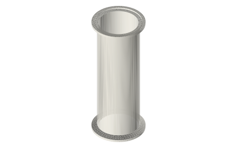 Tri-clamp spool, 1.5 and 2 inchflexure head clamps on its ferrule
Connects to
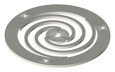 Planar spiral flexure bearingsleaves, spacers, clamp plates, hub washers
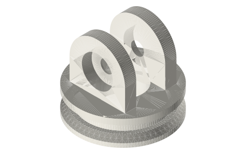 Tri-clamp power pistons and crank linkage-rod piston takes the plug
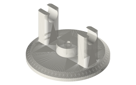 Tri-clamp displacers and engine headsdisplacer rod through the piston
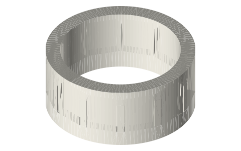 Moving-magnet linear alternator kitmagnet carrier on the tube rod
Alternatives
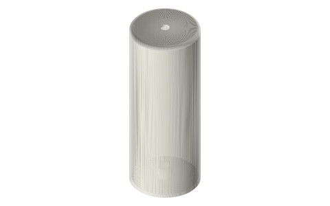 Free-piston Stirling corestand-alone liner version
Also needed
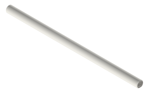 Stirling shafts and rodsØ3 displacer rod; printed tube rod for a mock-up
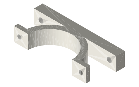 Spool hanger collarshang it from a 2020 crossbar
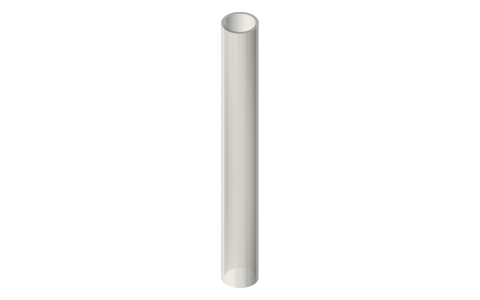 Hobby brass tube, 1/16–21/32 in and 1–12 mm,…5 mm tube piston rod
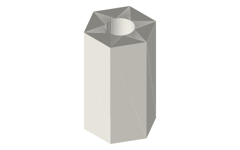 Threaded standoffs, M2.5 and M3M3 × 30 standoffs head to ring
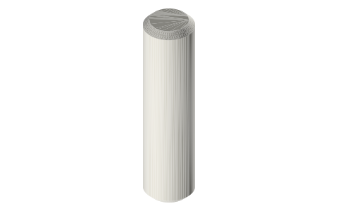 Dowel pins, 2–6 mmØ3 × 16 dowels lock the plug
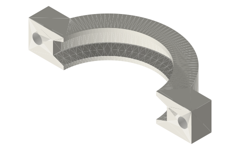 Tri-clamp clamps, hot-joint gaskets and heat shieldsclamp the head on
In these build lists
Beta Stirling, rhombic drive, 2 in tri-clampDisplacer and piston in one bore, two counter-rotating gears: the balanced one.Free-piston Stirling, 2 in tri-clampNo crank: displacer rod through the piston, both hung on spiral flexure stacks; …You might also need
Questions
How does the piston connect to a flexure bearing?
Through the piston plug: it sits in the open skirt, the wrist-pin dowels lock it, and its socket takes a 5 mm brass tube. The flexure leaf hubs clamp on that tube between two split hub collars; the leaf rims bolt to the flexure head.
How does the displacer rod get past the piston in a free-piston engine?
Through a dry 3 × 5 × 6 bushing (graphite-bronze or degreased sintered bronze) pressed in the crown of the -rod piston, then up the inside of the hollow tube piston rod to its own flexure stack on the ring above.
What flexure size for a 2 inch spool?
Ø80 leaves (hub Ø17.6) on the 2 in flexure head; Ø60 for 1.5 in, Ø100 for 3 in.
Can the free-piston engine run on printed flexures?
As a demonstrator, yes: 2 mm PETG leaves show the motion and survive thousands of cycles. For a running engine cut the 0.5 mm steel leaves from the DXF.