 Xem Studiomeasured geometry
Library › Hardware › Fasteners ·
Clevis pins with head, ISO 2341 (DIN 1444) forms A and B, d 3–100: head diameter and height, split-pin hole, le, radius + example pin models
What are the head diameter, head height and split-pin hole of an ISO 2341 clevis pin, and what size cotter pin goes with it? · Standard part · basis: Global Fastener's ISO 2341:1986 table for d 3 to 100 (26 sizes), ITA Fasteners' ISO 2341 B table for d 4 to 24 (agrees on every value), Amesweb for what each symbol is, one maker's inch rows (Sunhyings); ten example pin models as files
Also called: iso 2341 clevis pin, din 1444 clevis pin dimensions, clevis pin head diameter, 10 mm clevis pin head diameter, clevis pin split pin hole size, clevis pin 8 mm head height, clevis pin cotter pin size chart, iso 2341 b 10x50, clevis pin 12 mm dimensions, clevis pin 6 mm, clevis pin le min, clevis pin underhead radius, clevis pin form a vs form b, clevis pin step file
Exact dimensions. Every file is drawn at true size with no tolerance added. The holes and pins that meet another part are listed below under Mating features, with the fit each joint needs; open those by your process's clearance before making the part. Mating features
- length
- 18.0 mm
- width
- 18.0 mm
- height
- 54.0 mm
Notes
- ISO 2341 covers clevis pins with head, form A (plain) and form B (with a split-pin hole), d 3 to 100 mm. Columns in mm: d (nominal, h11) and its minimum limit, head dk h14 (max / min), head height k js14 (nominal, with its max / min), split-pin hole d1 H13 (nominal / max, B only), c max, e, le min and the under-head radius r. Global Fastener and ITA agree on d, dk, k, d1, c, e, le and r for every size 4 to 24 mm; the tolerance classes (h11, h14, js14, H13) are ITA's and Amesweb's headings, and d min and the max / min values are consistent with them (for example d 10 h11: 9.91 min).
- Symbols, from Amesweb's label list: c = end chamfer, e = head chamfer, le = 'end to centre' (the distance from the pin end to the centre of the split-pin hole) and r = under-head radius. The standard says le may in no case be smaller than the tabulated value (Amesweb, iTeh's page for the standard), so le is a minimum, not a fixed position. The sources read give the chamfer sizes c and e but not their angle, so the models leave the end and head chamfers off.
- Cotter size follows the hole: d1 is the split pin's nominal size (ISO 1234 split pins are sized by the hole, see split-pins-iso-1234). The size-to-pin ranges of ISO 1234 and the d1 of ISO 2341 line up for every one of the 26 sizes here (for example d 10 and d 12 both take 3.2 mm, d 24 and d 27 take 6.3 mm, d 70 to 100 take 13 mm).
- Inch rows (a maker's table citing ISO 2341 B / DIN 1444 and ASME B18.8.1): nominal diameter, its metric equivalent, head diameter, effective grip length range, hole diameter and recommended cotter pin; the page defines grip length as under the head to the centre of the cross hole, and gives h11 as the pin tolerance. One maker's values; the ASME standard was not read.
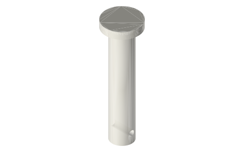
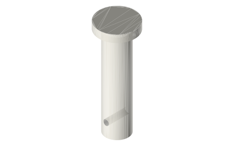
- Files: ten pins drawn at true size from the numbers above (form B at d 4, 5, 6, 8, 10, 12, 16, 20 and form A at d 6 and 10). The shank lengths (20, 25, 30, 40, 50, 60, 80, 100 mm) are Xem's examples; the commercial length series was not read for the full range. The hole axis is placed at le min from the pin end and the hole runs straight through the shank at d1 nominal. Pin ends and head are square (no chamfers). Lengths not listed: change the length in your CAD; the head and hole numbers do not depend on it.
- The existing page pins-clevises-and-joints has small model-work clevis pins (d 3 to 8) and a different set of split-pin and R-clip notes; this page is the ISO 2341 table for d 3 to 100.
Clevis pins with head, ISO 2341 (DIN 1444) forms A and B, d 3–100… size chart
| d nominal (mm, h11) | d min (mm) | head dk h14 max / min | head height k js14: nominal (max / min) | split-pin hole d1 H13: nominal / max | c max | e | le min | r |
|---|---|---|---|---|---|---|---|---|
| 3 | 2.94 | 5 / 4.7 | 1 (1.125 / 0.875) | 0.8 / 0.94 | 1 | 0.5 | 1.6 | 0.6 |
| 4 | 3.925 | 6 / 5.7 | 1 (1.125 / 0.875) | 1 / 1.14 | 1 | 0.5 | 2.2 | 0.6 |
| 5 | 4.925 | 8 / 7.64 | 1.6 (1.725 / 1.475) | 1.2 / 1.34 | 2 | 1 | 2.9 | 0.6 |
| 6 | 5.925 | 10 / 9.64 | 2 (2.125 / 1.875) | 1.6 / 1.74 | 2 | 1 | 3.2 | 0.6 |
| 8 | 7.91 | 14 / 13.57 | 3 (3.125 / 2.875) | 2 / 2.14 | 2 | 1 | 3.5 | 0.6 |
| 10 | 9.91 | 18 / 17.57 | 4 (4.15 / 3.85) | 3.2 / 3.38 | 2 | 1 | 4.5 | 0.6 |
| 12 | 11.89 | 20 / 19.48 | 4 (4.15 / 3.85) | 3.2 / 3.38 | 3 | 1.6 | 5.5 | 0.6 |
| 14 | 13.89 | 22 / 21.48 | 4 (4.15 / 3.85) | 4 / 4.18 | 3 | 1.6 | 6 | 0.6 |
| 16 | 15.89 | 25 / 24.48 | 4.5 (4.65 / 4.35) | 4 / 4.18 | 3 | 1.6 | 6 | 0.6 |
| 18 | 17.89 | 28 / 27.48 | 5 (5.15 / 4.85) | 5 / 5.18 | 3 | 1.6 | 7 | 1 |
| 20 | 19.87 | 30 / 29.48 | 5 (5.15 / 4.85) | 5 / 5.18 | 4 | 2 | 8 | 1 |
| 22 | 21.87 | 33 / 32.38 | 5.5 (5.65 / 5.35) | 5 / 5.18 | 4 | 2 | 8 | 1 |
| 24 | 23.87 | 36 / 35.38 | 6 (6.15 / 5.85) | 6.3 / 6.52 | 4 | 2 | 9 | 1 |
| 27 | 26.87 | 40 / 39.38 | 6 (6.15 / 5.85) | 6.3 / 6.52 | 4 | 2 | 9 | 1 |
| 30 | 29.87 | 44 / 43.38 | 8 (8.18 / 7.82) | 8 / 8.22 | 4 | 2 | 10 | 1 |
| 33 | 32.84 | 47 / 46.38 | 8 (8.18 / 7.82) | 8 / 8.22 | 4 | 2 | 10 | 1 |
| 36 | 35.84 | 50 / 49.38 | 8 (8.18 / 7.82) | 8 / 8.22 | 4 | 2 | 10 | 1 |
| 40 | 39.84 | 55 / 54.26 | 8 (8.18 / 7.82) | 8 / 8.22 | 4 | 2 | 10 | 1 |
| 45 | 44.84 | 60 / 59.26 | 9 (9.18 / 8.82) | 10 / 10.22 | 4 | 2 | 12 | 1 |
| 50 | 49.84 | 66 / 65.26 | 9 (9.18 / 8.82) | 10 / 10.22 | 4 | 2 | 12 | 1 |
| 55 | 54.81 | 72 / 71.26 | 11 (11.215 / 10.785) | 10 / 10.22 | 6 | 3 | 14 | 1 |
| 60 | 59.81 | 78 / 77.26 | 12 (12.215 / 11.785) | 10 / 10.22 | 6 | 3 | 14 | 1 |
| 70 | 69.81 | 90 / 89.13 | 13 (13.215 / 12.785) | 13 / 13.27 | 6 | 3 | 16 | 1 |
| 80 | 79.81 | 100 / 99.13 | 13 (13.215 / 12.785) | 13 / 13.27 | 6 | 3 | 16 | 1 |
| 90 | 89.78 | 110 / 109.13 | 13 (13.215 / 12.785) | 13 / 13.27 | 6 | 3 | 16 | 1 |
| 100 | 99.78 | 120 / 119.13 | 13 (13.215 / 12.785) | 13 / 13.27 | 6 | 3 | 16 | 1 |
| inch: 1/4 in (6 mm) | head Ø 0.375 in | grip length 0.50–2.00 in | hole Ø 0.076 in | cotter 1/16 in | ||||
| inch: 5/16 in (8 mm) | head Ø 0.438 in | grip length 0.75–3.00 in | hole Ø 0.106 in | cotter 3/32 in | ||||
| inch: 3/8 in (10 mm) | head Ø 0.500 in | grip length 1.00–4.00 in | hole Ø 0.106 in | cotter 3/32 in | ||||
| inch: 1/2 in (12 mm) | head Ø 0.625 in | grip length 1.00–5.00 in | hole Ø 0.141 in | cotter 1/8 in | ||||
| inch: 5/8 in (16 mm) | head Ø 0.812 in | grip length 1.50–6.00 in | hole Ø 0.141 in | cotter 1/8 in | ||||
| inch: 3/4 in (20 mm) | head Ø 0.938 in | grip length 2.00–8.00 in | hole Ø 0.172 in | cotter 5/32 in | ||||
| inch: 1 in (25 mm) | head Ø 1.250 in | grip length 2.50–10.00 in | hole Ø 0.203 in | cotter 3/16 in |
Mating features
Drawn at the exact size. Open press, slide, run and socket features by your process's clearance (tolerances by process); leave designed gaps and clamp fits as drawn.
| feature | exact | mates with | fit | files |
|---|---|---|---|---|
| split-pin hole d1 (form B) | 3 → Ø0.8, 4 → Ø1, 5 → Ø1.2, 6 → Ø1.6, 8 → Ø2, 10 and 12 → Ø3.2, 16 → Ø4, 20 → Ø5 mm (H13), axis le min from the pin end (4: 2.2, 6: 3.2, 10: 4.5, 20: 8) | ISO 1234 split pin whose nominal size equals the hole (see split-pins-iso-1234); the cross hole through the pin | slide | clevis-pin-iso-2341-b-* |
| pin shank d | Ø4, 5, 6, 8, 10, 12, 16, 20 mm (h11, nominal = maximum) | hole through the clevis (fork) and the link; the hole class is not in the sources read | run | clevis-pin-iso-2341-* |
Where the files are
Other publishers' files are linked, not hosted. "verify" = check the license at the link before commercial use.
| Global Fastener | ISO 2341:1986 clevis pins with head, types A and B, d 3 to 100: d min, dk max / min, d1, c, e, k, le min, r | web | Reference page; numbers only |
| ITA Fasteners | Clevis pins ISO 2341 B: d h11, dk h14, k js14, d1 H13, c max, e, le min, r for d 4 to 24 | web | Maker page; numbers only |
| Amesweb | Metric clevis pin dimensions: symbol labels d1, dk, dl, c (end chamfer), e (head chamfer), k, le (end to centre), r (underhead radius); d h11, dk h14, dl H13 (calculator; values not readable) | web | Reference page; labels only |
| Sunhyings | Industrial clevis pins ISO 2341 B / DIN 1444: inch rows 1/4 to 1 in with head diameter, grip length range, hole and recommended cotter pin (one maker's table) | web | Maker page; numbers only |
| ISO | ISO 2341:1986: Clevis pins with head (standard body catalogue page; the standard itself is paid) | web | Standard body catalogue page |
Free files
★ Free files 10 parts. Generated by Xem Studio from the standard; threads are plain cylinders at major diameter. CC BY 4.0. index.json
| clevis-pin-iso-2341-b-4x20 | clevis pin with head, ISO 2341 form B (with split-pin hole): shank Ø4 × 20 mm under the head (example length, Xem's choice), head Ø6 × 1 mm, under-head radius 0.6 mm, split-pin hole Ø1 across the shank with its axis 2.2 mm (le min) from the pin end (example position, le is a minimum in the standard); no end or head chamfer (their angle is not in the sources read) | STEP · STL |
| clevis-pin-iso-2341-b-5x25 | clevis pin with head, ISO 2341 form B (with split-pin hole): shank Ø5 × 25 mm under the head (example length, Xem's choice), head Ø8 × 1.6 mm, under-head radius 0.6 mm, split-pin hole Ø1.2 across the shank with its axis 2.9 mm (le min) from the pin end (example position, le is a minimum in the standard); no end or head chamfer (their angle is not in the sources read) | STEP · STL |
| clevis-pin-iso-2341-b-6x30 | clevis pin with head, ISO 2341 form B (with split-pin hole): shank Ø6 × 30 mm under the head (example length, Xem's choice), head Ø10 × 2 mm, under-head radius 0.6 mm, split-pin hole Ø1.6 across the shank with its axis 3.2 mm (le min) from the pin end (example position, le is a minimum in the standard); no end or head chamfer (their angle is not in the sources read) | STEP · STL |
| clevis-pin-iso-2341-b-8x40 | clevis pin with head, ISO 2341 form B (with split-pin hole): shank Ø8 × 40 mm under the head (example length, Xem's choice), head Ø14 × 3 mm, under-head radius 0.6 mm, split-pin hole Ø2 across the shank with its axis 3.5 mm (le min) from the pin end (example position, le is a minimum in the standard); no end or head chamfer (their angle is not in the sources read) | STEP · STL |
| clevis-pin-iso-2341-b-10x50 | clevis pin with head, ISO 2341 form B (with split-pin hole): shank Ø10 × 50 mm under the head (example length, Xem's choice), head Ø18 × 4 mm, under-head radius 0.6 mm, split-pin hole Ø3.2 across the shank with its axis 4.5 mm (le min) from the pin end (example position, le is a minimum in the standard); no end or head chamfer (their angle is not in the sources read) | STEP · STL |
| clevis-pin-iso-2341-b-12x60 | clevis pin with head, ISO 2341 form B (with split-pin hole): shank Ø12 × 60 mm under the head (example length, Xem's choice), head Ø20 × 4 mm, under-head radius 0.6 mm, split-pin hole Ø3.2 across the shank with its axis 5.5 mm (le min) from the pin end (example position, le is a minimum in the standard); no end or head chamfer (their angle is not in the sources read) | STEP · STL |
| clevis-pin-iso-2341-b-16x80 | clevis pin with head, ISO 2341 form B (with split-pin hole): shank Ø16 × 80 mm under the head (example length, Xem's choice), head Ø25 × 4.5 mm, under-head radius 0.6 mm, split-pin hole Ø4 across the shank with its axis 6 mm (le min) from the pin end (example position, le is a minimum in the standard); no end or head chamfer (their angle is not in the sources read) | STEP · STL |
| clevis-pin-iso-2341-b-20x100 | clevis pin with head, ISO 2341 form B (with split-pin hole): shank Ø20 × 100 mm under the head (example length, Xem's choice), head Ø30 × 5 mm, under-head radius 1 mm, split-pin hole Ø5 across the shank with its axis 8 mm (le min) from the pin end (example position, le is a minimum in the standard); no end or head chamfer (their angle is not in the sources read) | STEP · STL |
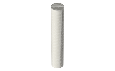
| clevis-pin-iso-2341-a-6x30 | clevis pin with head, ISO 2341 form A (without split-pin hole): shank Ø6 × 30 mm under the head (example length, Xem's choice), head Ø10 × 2 mm, under-head radius 0.6 mm; no end or head chamfer (their angle is not in the sources read) | STEP · STL |
| clevis-pin-iso-2341-a-10x50 | clevis pin with head, ISO 2341 form A (without split-pin hole): shank Ø10 × 50 mm under the head (example length, Xem's choice), head Ø18 × 4 mm, under-head radius 0.6 mm; no end or head chamfer (their angle is not in the sources read) | STEP · STL |
https://xemstudio.com/mcp to Claude, ChatGPT, Cursor or any MCP client (free, no account, one minute) and it can look up exact sizes, mating fits and free STEP/STL from every chat.Plain text: sheet.txt · JSON: /api/geometry?object=clevis-pins-iso-2341
Fits with
Questions
What are the head and hole of a 10 mm ISO 2341 clevis pin?
Head Ø18 (h14) × 4 mm, split-pin hole Ø3.2 (H13), le min 4.5 mm, under-head radius 0.6 mm (Global Fastener and ITA agree).
What cotter pin for a 12 mm clevis pin?
The ISO 2341 hole d1 is 3.2 mm, so a 3.2 mm split pin (ISO 1234 nominal size = hole size).
What is the difference between form A and form B?
Form A has no split-pin hole; form B has the cross hole for a split pin (iTeh's page for ISO 2341). The models include both.