 Xem Studiomeasured geometry
Library › Pre-assembled engines ·
Modular free-piston thermoacoustic engine, 2 in tri-clamp (stack sections and a clamp-in linear alternator)
A standing-wave thermoacoustic engine built from 2 in sanitary sections like Legos: closed hot section with its exchanger, hot joint, stack section with the ambient exchanger, optional thermal break, and the clamp-in linear alternator module whose sprung piston replaces the resonator tube.
He 10 bar, 550 °C hot gas, piston ±5 mm: 47 Hz, 10 W electric, 13 % of 81 W into the hot exchanger (20 % of Carnot) · onset 294 °C · air 10 bar 1.7 W · air 1 bar 0.11 W (model) · sections 60 + 68.65 + module 147
Exact dimensions. Every part is drawn at true size with no printing tolerance; each part's page lists its mating features and the fit each joint needs, so open those by your process's clearance before making the parts.
Long Earth Society build part. Complete parts list. The engines
56 parts, every one a file here · all STL URLs · Markdown · tick lines as you go (saved in this browser)
| subsystem | object | parts | qty | note | |
|---|---|---|---|---|---|
| None | 2020 aluminum extrusion | 2020-300 STEP · STL | 2 | uprights | |
| None | 2020 aluminum extrusion | 2020-200 STEP · STL | 2 | rails on the bench behind the uprights, clamped or screwed to the bench | |
| None | L corner brackets for 20 | corner-bracket-20 STEP · STL | 4 | two per upright | |
| None | Button head socket screws | button-m5x10 STEP · STL | 8 | bracket screws | |
| None | Flat washers | washer-m5 STEP · STL | 8 | ||
| None | Drop-in T-nuts for 20 | tnut-dropin-20-m5 STEP · STL | 10 | 8 brackets, 2 for the hanger | |
| None | Spool hanger collars | hanger-2in-tab STEP · STL | 1 | on the stack section, right under the jacket (the cool end of the stack) | |
| None | Spool hanger collars | hanger-2in-plain STEP · STL | 1 | ||
| None | Socket head cap screws | shcs-m5x16 STEP · STL | 2 | hanger bar into the uprights' T-nuts | |
| None | Socket head cap screws | shcs-m4x20 STEP · STL | 2 | close the hanger on the tube | |
| None | Hex nuts | nut-m4 STEP · STL | 2 | hanger ears | |
| None | Torch stand for a horizontal tri-clamp h | torch-stand-40 STEP · STL | 1 | on the bench under the shroud's flue, 25 below it; the heat source is a propane or butane torch head in the ring | |
| None | Set screws (grub screws) | set-m4x10 STEP · STL | 3 | centre the torch head in the ring | |
| None | Thermoacoustic hot-head shroud | ta-shroud-2in-front STEP · STL | 1 | flame shroud round the hot exchanger, its band 10.35 to 50.35 below the hot section's face; flue down to the torch | |
| None | Thermoacoustic hot-head shroud | ta-shroud-2in-back STEP · STL | 1 | ||
| None | Socket head cap screws | shcs-m4x25 STEP · STL | 2 | shroud ears | |
| None | Hex nuts | nut-m4 STEP · STL | 2 | shroud ears | |
| None | Thermoacoustic fin sleeve for the flame- | ta-fin-sleeve-half-2in-34-r36 STEP · STL | 2 | optional heat exchanger: fin sleeve over the hot exchanger, inside the shroud band | |
| None | Socket head cap screws | shcs-m4x12 STEP · STL | 2 | optional, with the fin sleeve: its ears | |
| None | Hex nuts | nut-m4 STEP · STL | 2 | optional, with the fin sleeve: its ears | |
| None | Tri-clamp cups | cup-2in-60 STEP · STL | 1 | HOT SECTION: closed end down; the hot cavity and the hot exchanger | |
| None | Thermoacoustic hot-cavity liners | ta-hot-liner-2in-17 STEP · STL | 1 | hot section: stands on the closed end | |
| None | Thermoacoustic heat exchangers | heat-exchanger-hot-2in STEP · STL | 4 | hot section: four discs on the liner, plates all the same way, the top one flush with the face | |
| None | Tri-clamp flat gasket (hot joint | hot-gasket-2in STEP · STL | 1 | J1, the hot joint: flat ring between the hot and stack sections; it runs at about the hot-exchanger temperature (550 °C design): rated for at least 600 °C | |
| None | High-pressure bolted sanitary clamp | hp-clamp-2in | 1 | J1: high-pressure bolted 2 in clamp, rated at the J1 temperature for the charge used (not drawn; published ratings stop at 121 °C) | |
| None | Thermoacoustic stack-section spools | spool-2in-68.65mm STEP · STL | 1 | STACK SECTION: plain 2 in spool cut to length | |
| None | Thermoacoustic stack for tri-clamp spool | stack-spiral-2in-50-g1.0 STEP · STL | 1 | stack section: stands on the hot exchanger, its lower 1.7 inside J1's ring; it must take 550 °C at its hot end | |
| None | Thermoacoustic heat exchangers | heat-exchanger-cold-2in STEP · STL | 1 | stack section: ambient exchanger on the stack's cold end | |
| None | Thermoacoustic bore spacers and liners f | ta-spacer-2in-8.4 STEP · STL | 1 | stack section: ambient exchanger to the J2 gasket lip | |
| None | Thermoacoustic water jacket | ta-jacket-half-2in-14 STEP · STL | 2 | optional heat exchanger: water jacket over the ambient exchanger, 9.35 below the stack section's top face; or cool that band any way you like | |
| None | Socket head cap screws | shcs-m4x25 STEP · STL | 2 | optional: jacket ears (only with the jacket) | |
| None | Hex nuts | nut-m4 STEP · STL | 2 | optional: jacket ears (only with the jacket) | |
| None | Tri-clamp thermal-break spacer | break-spacer-2in-25.4 STEP · STL | 1 | choose one cold joint, B (thermal-break spacer): between the stack section and the alternator's face A, at the cooling water's temperature; costs power (dead volume). A (the build): face A straight on the stack section | |
| None | Tri-clamp gasket | tc-gasket-2in STEP · STL | 1 | choose one cold joint, B (thermal-break spacer): its second Type B joint | |
| None | High-pressure bolted sanitary clamp | hp-clamp-2in | 1 | choose one cold joint, B (thermal-break spacer): its second high-pressure clamp (not drawn) | |
| None | Linear alternator module spools | spool-2in-42mm-bored-48.00 STEP · STL | 1 | ALTERNATOR MODULE (closed, standard build): face A (to the engine) and the piston's cylinder | |
| None | 2 in × 3 in spool with the bore finished | spool-2in-3in-bored-48.00 STEP · STL | 1 | module: the alternator section: magnet carrier inside, stator outside | |
| None | Linear alternator module spools | spool-2in-25.4mm STEP · STL | 1 | module: face B end: leaf 2's hub travel | |
| None | Tri-clamp flexure leaf | leaf-2in-piston-t0.8 STEP · STL | 2 | module: joints 1 and 2; leaf 2 turned over (opposite hand) | |
| None | Tri-clamp half gasket for a clamped leaf | leaf-half-gasket-2in-w0.45 STEP · STL | 4 | module: two per leaf, beads outward | |
| None | Linear alternator module mover | la-piston-cup-48x24 STEP · STL | 1 | module: in the 42 bored spool, crown toward face A | |
| None | Linear alternator module mover | la-tube-rod-18x14x108.15 STEP · STL | 1 | module: pressed into the cup's socket; through both leaves | |
| None | Linear alternator module mover | la-magnet-carrier-47x56 STEP · STL | 1 | module: pressed on the tube rod, centred under the stator | |
| None | Neodymium disc magnets | magnet-12x3 STEP · STL | 40 | module: 4 rows of 10 in the carrier, faces out: S, N, N, S from face A | |
| None | Leaf hub collars | fpse-collar-18x28 STEP · STL | 4 | module: either side of each leaf's hub on the tube rod | |
| None | Set screws (grub screws) | set-m3x4 STEP · STL | 4 | module: one grub per collar | |
| None | Moving-magnet linear alternator stator o | fpse-stator-pack-43deg STEP · STL | 8 | module: round the 3 in bored spool at the magnets' centre | |
| None | Moving-magnet linear alternator stator o | fpse-bobbin-65 STEP · STL | 1 | module: between the teeth; slid over the spool's flange first | |
| None | Moving-magnet linear alternator stator o | fpse-coil-300t STEP · STL | 1 | module: 300 turns of 0.71 mm enamelled wire on the bobbin; the leads leave through the housing | |
| None | Moving-magnet linear alternator stator o | fpse-stator-housing-half STEP · STL | 2 | module: clamp the packs onto the tube | |
| None | Socket head cap screws | shcs-m4x20 STEP · STL | 4 | module: stator housing ears | |
| None | Hex nuts | nut-m4 STEP · STL | 4 | module: stator housing ears | |
| None | High-pressure bolted sanitary clamp | hp-clamp-2in | 4 | module: high-pressure bolted 2 in clamps: joints 1 and 2, face B under the cap, and face A on the stack section (J2) (not drawn); rated above the 15 bar gauge relief setting | |
| None | Tri-clamp gasket | tc-gasket-2in STEP · STL | 2 | module: Type B at face A (J2, on the stack section) and face B (under the cap) | |
| None | Tri-clamp port cap | port-cap-2in-4x-npt18 STEP · STL | 1 | module: closes face B (the bounce space): fill valve, pressure gauge, relief valve, and a plug or pressure transducer; off when face B clamps into a loop | |
| None | NPT male thread envelopes 1/8 to 1 in (A | npt-1-8-male STEP · STL | 4 | module: the 1/8 NPT stems of the fill valve, gauge, relief valve and plug (bodies are the builder's choice) |
Assembled engine
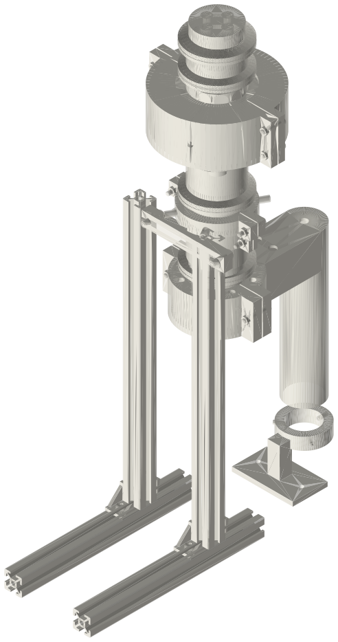
A modular free-piston thermoacoustic engine in 2 in tri-clamp sections, hot end down on a 2020 stand: a 60 mm closed hot cup holding its hot exchanger inside a flame shroud whose flue comes down to a torch stand, a 68.65 mm stack section with the stack and ambient exchanger under a water jacket, and the closed clamp-in linear alternator module on top; about 140 × 321 × 492 mm.
Assembly STEP (9.7 MB) · STL (8.7 MB) · 162 parts
Build order
- Stand: rails, uprights, brackets; torch stand on the bench in front, ring toward the back; torch head in the ring with its three M4 set screws.
- Hot section, closed end down: liner on the closed end, four hot exchanger discs on it (plates all the same way), the top one flush with the face.
- J1: flat hot ring on the hot section's face. Stack section on top: stack into its lower end first (1.7 mm proud of the face), ambient exchanger, 8.4 spacer; lower the section onto the ring so the stack stands on the hot exchanger; high-pressure clamp.
- Optional: fin sleeve halves round the hot exchanger band (2 × M4 × 12); shroud halves round it with the flue to the front, down to the torch (2 × M4 × 25).
- Hanger on the stack section right under where the jacket goes, bar to the uprights. Optional water jacket 9.35 below the stack section's top face (2 × M4 × 25).
- Cold joint B only (thermal-break spacer): Type B gasket, the 25.4 spacer, clamp.
- The closed linear alternator module, built and checked on its own list (crown 9.00 below face A): Type B gasket on the stack section's top face (or the break spacer's), module face A down onto it, high-pressure clamp. Port cap, fill valve, gauge and relief valve on face B.
- Load resistor and series capacitor on the coil before the burner is lit. Charge slowly through the fill valve (or run at 1 bar until J1 is verified), cooling water on, then light the torch.
Questions
What does each section do, and how long is it?
Hot section: takes the heat: hot cavity (the gas spring at the hot end) and the 40 mm hot exchanger under the flame shroud (60 mm); J1 hot joint: seals at about 550 °C; the stack passes into its bore (1.7 mm); stack section: holds the temperature gradient (stack) and rejects heat (ambient exchanger, jacket) (68.65 mm); thermal break (optional): insulates the alternator from the stack section; costs power (25.4 mm); piston (in the module): the module's Ø48 clearance-seal piston cup in its 42 mm bored spool is the engine piston (42 mm); linear alternator module: mass-spring of the free piston (flexures, bounce gas) and the generator (147 mm)
How much power does it make?
Model: 10 W electric at 13 % on helium at 10 bar with 550 °C hot gas and ±5 mm stroke; 1.7 W on air at 10 bar; 0.11 W on air at 1 bar. It is a modest engine: the free-piston Stirling generator on this site makes several times more from the same alternator.
Where does the thermal break go?
At the cold joint, J2, and only as a spacer with its own two clamps: the hot joint runs at about 550 °C, too hot for an insulating ring rated to about 260 °C, and a ring in a single joint is bridged by the clamp anyway. The hot joint gets a flat ring rated for at least 600 °C.
What changes when I swap or extend a section?
Hot section cup-2in-60 (the build): 47 Hz, 10.2 W, 12.7 %; hot section cup-2in-90 (liner 47): 46 Hz, 11.4 W, 11.6 %; hot section cup-2in-120 (liner 77): 45 Hz, 11.6 W, 10.2 %; hot section closed-spool-2in-152.4 (liner 109.4): 44 Hz, 11.3 W, 8.9 %; stack section 30 (48.65 spool): 49 Hz, 14.3 W, 8.9 %; stack section 40 (58.65 spool): 48 Hz, 12.0 W, 11.0 %; thermal-break spacer added (J2 → 25.4 + one joint): 45 Hz, 4.4 W, 6.4 %; 3 in spool added on the cold side: 42 Hz, 0.1 W, 0.1 %; 6 in spool added on the cold side: 40 Hz, 0.0 W, 0.0 % (helium 10 bar, model).
Is the module's piston the engine piston?
Yes. The gas column is much shorter than a wavelength, so the piston can be anywhere along it; a separate piston and rod would only add a seal, mass and dead volume.
Why is the efficiency low, and what is better?
A standing-wave stack works through imperfect thermal contact and cannot reach the efficiency of a regenerator with traveling-wave phasing. A regenerator plus a feedback path (a thermoacoustic-Stirling engine, as the twin-piston and ring engines on this site) or a free-piston Stirling engine does much better from the same heat.
Agents: each row's object has /api/geometry?object=slug and the MCP tool get_free_files; the STL list above is every part.